
 EN
EN
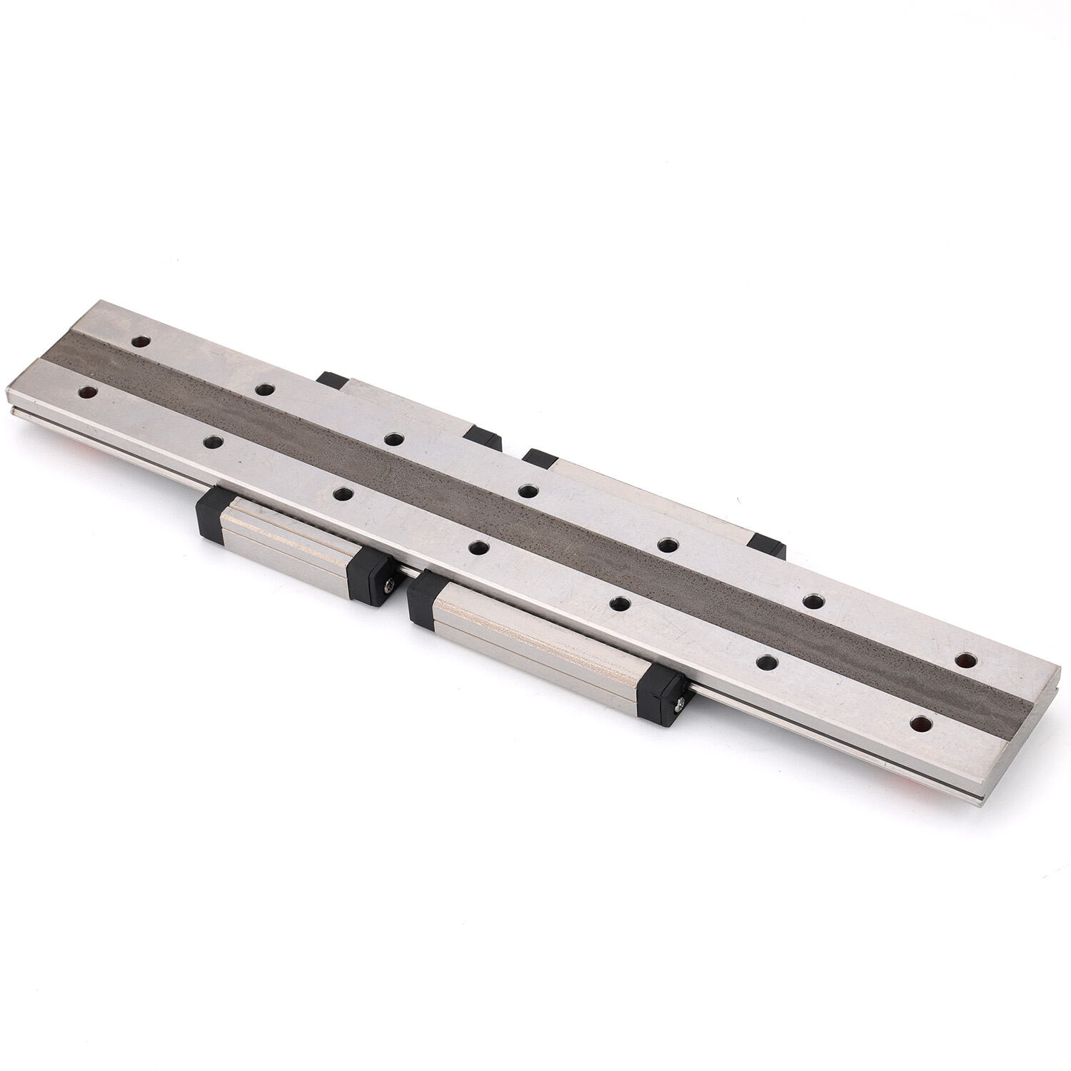
Selecting the optimal linear guide rails for CNC machines represents a critical engineering decision that directly influences machining accuracy, operational lifespan, and production efficiency. CNC systems demand linear motion components capable of maintaining micron-level precision under continuous dynamic loads while resisting contamination from metal chips, coolant exposure, and thermal fluctuations inherent to subtractive manufacturing environments. The choice between profiled rail systems, recirculating ball designs, and roller-type configurations depends on specific application parameters including load capacity requirements, speed profiles, positional repeatability tolerances, and environmental severity. Understanding how different linear guide rail architectures perform under CNC-specific stress conditions enables engineers to match guide rail characteristics with machine tool requirements, avoiding premature wear, positional drift, or catastrophic failure that compromises part quality and production uptime.
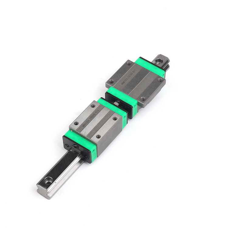
CNC machine builders and retrofit specialists typically evaluate linear guide rails through the lens of load-carrying geometry, precision retention characteristics, contamination resistance, and maintenance accessibility. Profiled rail systems with steel hardened raceways offer superior moment load capacity and system rigidity, making them particularly suitable for heavy cutting operations on machining centers and vertical lathes. Ball-based recirculating systems provide the lowest friction coefficients and highest speed potential, favored in high-velocity applications like wire EDM machines and high-speed milling centers. Roller-type linear guide rails deliver maximum load capacity and shock resistance, preferred for portal mills and gantry routers processing hard materials. The selection process must also account for preload adjustment capabilities, seal effectiveness against swarf ingress, lubrication interval requirements, and replacement part availability—factors that collectively determine total cost of ownership across the machine's operational life.
Load Capacity Considerations for CNC Linear Motion Systems
Static and Dynamic Load Rating Requirements
CNC applications impose complex loading conditions on linear guide rails that extend beyond simple vertical or horizontal forces. Machining operations generate combined radial loads from cutting forces, moment loads from overhanging tool assemblies or workpiece fixtures, and axial preload forces that maintain bearing contact. Profiled rail systems excel in managing these multi-directional loads through their four-point contact ball arrangements or cross-roller configurations, distributing forces across extended raceway surfaces. When evaluating linear guide rails for specific CNC applications, engineers must calculate combined load factors using manufacturer-provided formulas that account for all force vectors simultaneously, ensuring selected rail sizes maintain adequate safety margins under worst-case cutting scenarios.
Dynamic load ratings prove particularly critical for CNC systems executing repetitive motion cycles over extended operational periods. The relationship between applied loads and bearing life follows predictable curves defined by ISO standards, where doubling the load typically reduces expected travel distance by a factor of eight. Heavy-duty machining centers processing cast iron or titanium components require linear guide rails with dynamic load capacities substantially exceeding calculated forces to achieve target L10 life expectancies of 20,000 hours or more. Conversely, light-duty applications like PCB drilling machines or small-format laser engravers can utilize compact rail profiles with lower load ratings, optimizing cost while maintaining adequate service life for their lighter operational demands.
Moment Load Management and System Rigidity
Moment loads generated by offset cutting forces or asymmetric workpiece mounting create rotational stresses that challenge linear guide rail stability. CNC vertical machining centers with tall Z-axis configurations experience significant pitching moments as spindle-mounted cutting tools extend beyond the guideway centerline. Wide-block profiled linear guide rails distribute these moments across elongated ball contact patterns, maintaining carriage parallelism even under eccentric loading. Four-rail configurations on large gantry machines provide even greater moment resistance by increasing the effective moment arm between parallel guide rail pairs, though this approach demands precise rail alignment during installation to avoid binding or premature wear.
System rigidity directly correlates with achievable surface finishes and dimensional tolerances in CNC machining operations. Linear guide rails with preloaded ball or roller elements eliminate internal clearances that would otherwise permit microscopic deflections under cutting forces. Heavy preload classes sacrifice some speed capability and increase friction but deliver the minimal elastic deformation essential for precision boring, reaming, or fine grinding operations. Medium preload configurations balance rigidity against frictional heat generation, suitable for general-purpose milling and turning applications. Light preload or clearance fits serve high-speed, low-load applications where minimal resistance matters more than absolute positional stiffness, such as rapid positioning moves between cutting passes.
Precision Retention and Accuracy Performance Factors
Straightness and Parallelism Specifications
The geometric accuracy of linear guide rails fundamentally limits the precision achievable by CNC machines built upon them. Manufacturers specify straightness tolerances for individual rails and parallelism tolerances for matched pairs, typically ranging from 5 microns per 300mm for standard precision grades to 2 microns per 300mm for high-precision classifications. CNC applications demanding tight positional repeatability—such as coordinate measuring machines or precision grinding centers—require high-precision grade linear guide rails with corresponding installation procedures that preserve factory straightness through careful mounting surface preparation and torque sequencing. Standard precision rails suffice for general machining operations where final dimensional accuracy depends more heavily on thermal stability and ballscrew positioning than guide rail geometry.
Parallel installation of multiple linear guide rails introduces additional com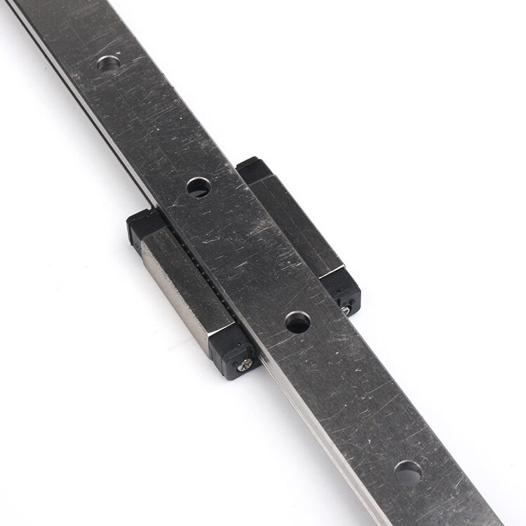 plexity in CNC system accuracy. When dual rails support a single moving carriage, any parallelism deviation between rail mounting surfaces translates into internal binding forces that increase friction, generate heat, and accelerate wear. Precision-ground machine beds or carefully scraped cast iron bases provide the flatness foundation necessary for successful parallel rail installation. Some CNC builders employ matched rail sets where manufacturers measure and pair rails with complementary height deviations, enabling parallel mounting even on base surfaces with minor irregularities. This matching process proves particularly valuable in large machine retrofits where existing bed surfaces cannot economically be reground to ideal flatness specifications.
Repeatability Performance Under Dynamic Conditions
Positional repeatability distinguishes between a guide rail's ability to return to the same position repeatedly versus its absolute accuracy relative to a theoretical straight line. CNC machining operations depend more critically on repeatability than absolute accuracy, since workpiece datum references and tool offsets compensate for systematic position errors. High-quality linear guide rails achieve sub-micron repeatability through preload mechanisms that eliminate backlash and through precision-ground raceways that maintain consistent ball or roller contact geometry. Over operational life, repeatability degrades more slowly than absolute accuracy as wear gradually removes raceway material, making repeatability retention a key indicator of guide rail quality and appropriate preload selection.
Dynamic repeatability testing under simulated CNC operating conditions reveals performance characteristics absent from static specifications. Acceleration-deceleration cycles generate inertial forces that momentarily separate balls from raceways in poorly preloaded systems, creating micro-impacts that degrade precision over time. Temperature gradients from frictional heating cause differential thermal expansion between rails and mounting structures, introducing temporary position errors during thermal equilibration periods. Superior linear guide rails for CNC applications incorporate design features addressing these dynamic challenges: optimized ball spacing that maintains contact throughout acceleration cycles, raceway materials with thermal expansion coefficients matched to common machine bed materials, and seal configurations that exclude contaminants without generating excessive frictional heat.
Environmental Protection and Contamination Resistance
Seal Design and Ingress Prevention
CNC machining environments subject linear guide rails to continuous assault from metal chips, abrasive grinding swarf, coolant spray, and hydraulic mist. Standard contact seals provide basic protection adequate for clean assembly operations or electronic component handling but prove insufficient for metal-cutting applications. Heavy-duty CNC applications demand linear guide rails equipped with multi-stage sealing systems combining scraper seals that remove large particles, contact seals that block fine dust, and labyrinth designs that create tortuous paths impeding liquid ingress. Some specialized CNC configurations employ pressurized air curtains or positive-pressure bellows that surround guide rails entirely, preventing contaminant approach through continuous outward airflow.
The effectiveness of seal systems directly correlates with maintenance interval lengths and operational lifespan in demanding CNC environments. Abrasive aluminum swarf from high-volume machining operations can infiltrate inadequately sealed linear guide rails within hours, acting as lapping compound that rapidly degrades raceway surfaces and increases clearances. Coolant penetration introduces corrosion risks and contaminates lubricants, reducing their load-carrying effectiveness. CNC machine builders must balance seal effectiveness against the frictional resistance and heat generation that intensive sealing introduces, particularly in high-speed applications where seal drag can limit achievable traverse rates or require additional cooling provisions to dissipate seal-generated heat.
Lubrication System Integration
Proper lubrication proves essential for linear guide rails operating in CNC environments, simultaneously reducing friction, dissipating heat, protecting against corrosion, and flushing away fine contaminants. Manual grease lubrication suits low-duty-cycle machines or short-stroke applications but proves impractical for production CNC systems operating continuous shifts. Centralized automatic lubrication systems with programmable dispensing intervals maintain optimal lubricant films across multiple linear guide rails simultaneously, ensuring consistent performance and eliminating operator-dependent maintenance variability. Oil mist lubrication provides superior cooling and contamination flushing but requires containment systems to prevent workplace contamination and environmental discharge.
Lubricant selection for CNC linear guide rails must account for operating temperature ranges, contamination levels, and compatibility with existing machine lubricants and coolants. High-viscosity greases provide excellent load-carrying capacity and seal-retention properties but generate higher friction at cold startup and may not distribute effectively across long rail lengths. Low-viscosity oils minimize friction and facilitate automatic dispensing but require more frequent replenishment and provide less protection against shock loads. Specialized CNC lubricants incorporate extreme-pressure additives that form protective films under boundary lubrication conditions, solid lubricant suspensions that continue providing protection even after carrier fluids evaporate, and corrosion inhibitors that neutralize acidic contaminants from water-soluble coolants.
Speed Capability and Acceleration Performance
Velocity Limitations and Frictional Characteristics
Maximum traverse speeds achievable with linear guide rails depend on ball or roller orbital velocity limits, cage separator materials, and frictional heat generation rates. Standard ball-type linear guide rails typically support continuous velocities up to 5 meters per second with intermittent capability to 8 meters per second, adequate for most CNC machining center rapids. High-speed variants with optimized ball circulation paths and synthetic cage materials extend continuous speed capabilities beyond 10 meters per second, enabling wire EDM machines and high-speed milling centers to minimize non-cutting time. Roller-type guide rails sacrifice some speed capability due to higher inertial masses but compensate with superior load capacity and shock resistance valuable in heavy-cutting portal mills.
Frictional characteristics of linear guide rails influence both speed capability and positioning accuracy in CNC applications. Starting friction exceeding running friction creates stick-slip behavior at low velocities, introducing servo instability and surface finish degradation during contouring operations. High-quality linear guide rails for CNC use maintain friction coefficients below 0.003 through precision-ground raceways, optimized ball spacing, and appropriate preload selection. Some manufacturers offer special low-friction variants with diamond-like carbon coatings or specialized ball materials that further reduce resistance, enabling ultra-precise positioning in applications like laser direct structuring or micro-milling where even microscopic stick-slip vibrations compromise results.
Acceleration Response and Settling Time
CNC productivity depends significantly on rapid acceleration between cutting positions and quick settling to positional stability before initiating cuts. Linear guide rails contribute to or constrain these dynamics through their mass, friction characteristics, and structural damping properties. Lightweight aluminum or composite carriages reduce moving mass, enabling higher accelerations with given servo motor torque capacity. However, these lightweight designs may exhibit reduced structural damping, extending settling times after rapid moves. Heavy steel carriages provide superior vibration damping but require larger servo motors and longer acceleration distances, trading quick response for stability during cutting.
System-level acceleration capability depends on matching linear guide rail characteristics with ballscrew pitch, servo motor sizing, and control system tuning parameters. Fine-pitch ballscrews combined with low-friction linear guide rails enable aggressive acceleration profiles that minimize cycle times in high-mix, low-volume production scenarios where machines spend significant time repositioning between features. Coarse-pitch screws with higher-preload guide rails suit heavy-cutting applications where positional stability during cutting matters more than rapid positioning. Advanced CNC control systems with adaptive tuning can optimize motion profiles for different operations, using aggressive acceleration for rapid positioning moves while smoothly transitioning to damped motion profiles during precision contouring, extracting maximum capability from underlying linear guide rail systems.
Installation Precision and Mounting Methodology
Base Surface Preparation Requirements
The accuracy achievable with even the highest-precision linear guide rails depends fundamentally on mounting surface preparation quality. CNC machine beds must provide flatness within specified tolerances—typically 10 microns per meter for standard applications, tightening to 5 microns per meter for high-precision machines. Surface grinding, precision planing, or hand scraping achieves these demanding specifications on cast iron or fabricated steel structures. Insufficient base flatness forces linear guide rails to conform to underlying surface irregularities during bolt tightening, introducing internal stresses that accelerate wear, increase friction, and compromise the geometric accuracy that precision rails theoretically provide.
Mounting hole location accuracy proves equally critical when installing linear guide rails on CNC machines. Manufacturers specify hole position tolerances typically within ±0.05mm, achievable through precision drilling on CNC machining centers or through template-guided manual operations. Oversized mounting holes with slip-fit bolts permit minor adjustment during installation, allowing technicians to optimize rail alignment using dial indicators or laser alignment systems before final torquing. Some CNC builders employ dowel pin registration between rails and beds for maximum positional repeatability during maintenance replacement, though this approach demands exceptional hole location accuracy during initial machine construction.
Alignment Verification and Adjustment Procedures
Post-installation verification ensures linear guide rails meet geometric specifications essential for CNC precision. Straightness measurement using precision levels, straightedges, or laser interferometers quantifies deviation from ideal geometry across rail length. Parallel installations require additional verification measuring distance variation between rail pairs, typically maintaining parallelism within 0.02mm across the full travel length. Discovered deviations sometimes respond to selective shimming beneath rail mounting surfaces, using precision ground shims in 0.01mm increments to compensate for base surface irregularities without inducing excessive rail bending stress.
Dynamic alignment testing under simulated operating conditions reveals issues invisible during static measurement. Running a carriage assembly along linear guide rails while monitoring friction force variations identifies localized tight spots or misalignment conditions. Temperature monitoring during extended operation cycles detects excessive frictional heating from misalignment or improper preload. Precision indicator measurements at multiple carriage positions quantify repeatability and reveal any stick-slip tendencies at low velocities. These comprehensive verification procedures ensure installed linear guide rails deliver the performance specifications CNC applications demand before committing machines to production service.
FAQ
What factors most influence linear guide rail selection for CNC machining centers?
The most critical selection factors include load capacity requirements based on cutting forces and component weights, required positional accuracy and repeatability for target part tolerances, environmental protection needs based on chip and coolant exposure, and desired traverse speeds for productivity optimization. Machining centers processing aluminum typically prioritize speed capability and contamination resistance, while heavy-duty machines cutting steel or titanium emphasize load capacity and rigidity. Precision grinding applications demand the highest accuracy grades with minimal deflection under cutting forces, while roughing mills accept standard precision grades focusing instead on durability and maintenance interval length.
How does preload selection affect CNC linear guide rail performance?
Preload selection directly influences system rigidity, friction characteristics, and operational lifespan. Heavy preload eliminates all internal clearance, maximizing stiffness for precision boring or grinding operations but increasing friction, heat generation, and wear rates. Medium preload balances adequate rigidity for general milling and turning against acceptable friction levels and extended bearing life. Light preload or slight clearance fits suit high-speed, low-load applications prioritizing minimal resistance over absolute positional stiffness. Incorrect preload selection causes premature failure—insufficient preload permits vibration and impact loading that damages raceways, while excessive preload generates heat that breaks down lubricants and accelerates wear.
Can linear guide rails be successfully retrofitted onto older CNC machines?
Linear guide rails can successfully replace worn box ways or degraded original guide systems on older CNC machines, often dramatically improving accuracy, speed capability, and maintenance requirements. However, successful retrofits require careful engineering to address mounting surface preparation, dimensional compatibility with existing ballscrews and servo systems, and proper alignment procedures. The existing machine bed must provide adequate structural rigidity and flatness, sometimes necessitating grinding or scraping operations before rail installation. Retrofit projects must also verify that existing servo motors provide sufficient torque for potentially different friction characteristics and that control systems accommodate any changes in positional feedback resolution or maximum velocity capabilities resulting from the guide rail upgrade.
What maintenance practices extend linear guide rail life in CNC applications?
Effective maintenance combines proper lubrication intervals, contamination exclusion, and periodic inspection protocols. Automatic lubrication systems ensure consistent lubricant replenishment according to operating hours or cycle counts, preventing the lubricant starvation that causes rapid wear. Regular seal inspection and replacement maintains contamination barriers before degradation permits swarf ingress. Periodic wiper cleaning removes accumulated chips before they breach seal systems. Friction force monitoring detects increasing resistance indicating developing problems before catastrophic failure occurs. Temperature monitoring identifies lubrication failures or misalignment issues through abnormal heating. Comprehensive maintenance documentation tracking these parameters enables predictive replacement before precision degradation affects part quality, minimizing unplanned downtime while extracting maximum service life from linear guide rail investments.
Table of Contents
- Load Capacity Considerations for CNC Linear Motion Systems
- Precision Retention and Accuracy Performance Factors
- Environmental Protection and Contamination Resistance
- Speed Capability and Acceleration Performance
- Installation Precision and Mounting Methodology
-
FAQ
- What factors most influence linear guide rail selection for CNC machining centers?
- How does preload selection affect CNC linear guide rail performance?
- Can linear guide rails be successfully retrofitted onto older CNC machines?
- What maintenance practices extend linear guide rail life in CNC applications?