
 EN
EN
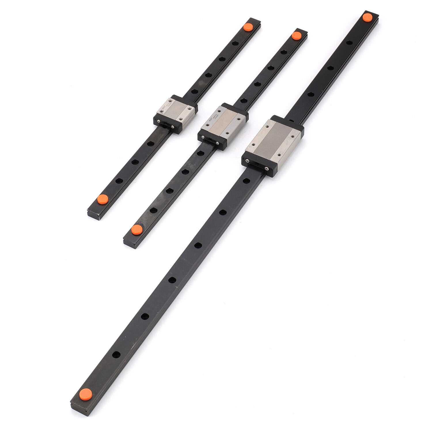
In precision manufacturing and automation, the mechanical components that govern motion quality are often the deciding factor between acceptable output and truly accurate results. A linear guide is one of those foundational components — a precision rail and carriage system designed to constrain motion to a single axis while minimizing deviation, play, and friction. When engineers ask how machine accuracy can be improved, the answer frequently points back to the quality and design of the linear guide system installed in the machine.
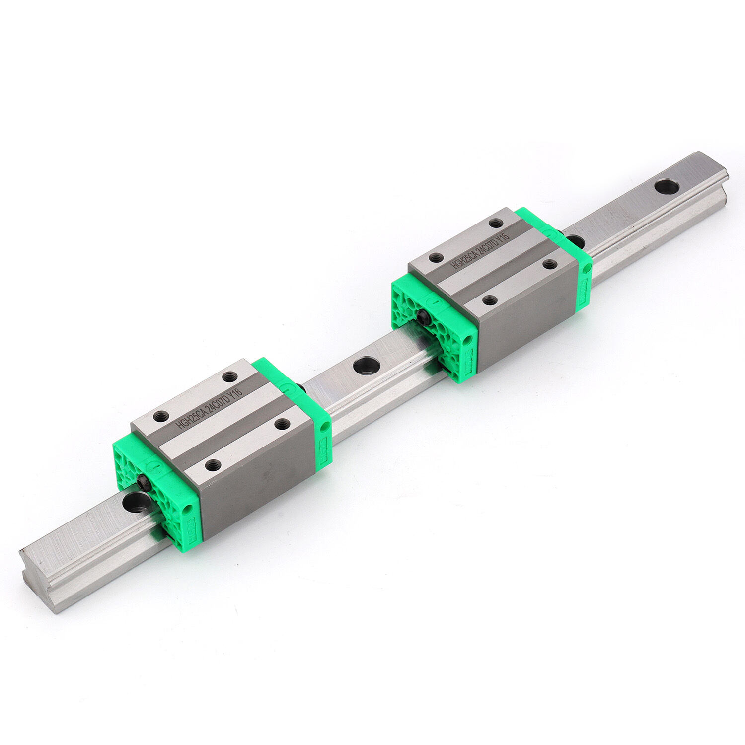
Understanding how a linear guide contributes to machine accuracy requires looking beyond the component itself and examining how it interacts with load, speed, alignment, and structural rigidity. This article breaks down the specific mechanisms through which a linear guide improves positional accuracy, repeatability, and overall motion quality in industrial machines — from CNC machining centers to semiconductor handling equipment and high-speed assembly systems.
The Mechanical Basis of Accuracy in Linear Motion
How Constrained Motion Reduces Positional Error
Machine accuracy depends on the ability to move a tool, workpiece, or sensor to a precise location and return to that location consistently. Any deviation from the intended path — whether caused by friction, mechanical play, or structural flex — introduces error. A linear guide addresses this by providing a geometrically controlled path that physically constrains the moving carriage to one degree of freedom.
The rail of a linear guide is ground to tight dimensional tolerances, and the carriage rides on recirculating rolling elements — typically balls or rollers — that maintain consistent contact with the rail's raceways. This rolling contact geometry eliminates the lateral drift and angular deviation that would otherwise accumulate during repeated traversals. The result is a motion path that closely matches the intended axis, reducing positional error at every point along the stroke.
In practical terms, a well-selected linear guide can achieve straightness tolerances in the range of a few micrometers per meter of travel. For machines where cutting depth, sensor positioning, or assembly placement must be held to tight tolerances, this level of geometric control is not optional — it is the foundation of the machine's accuracy specification.
Rolling Elements and the Elimination of Stick-Slip
One of the most damaging sources of positioning error in older sliding-contact systems is stick-slip — the irregular motion that occurs when static friction suddenly gives way to kinetic friction. This phenomenon causes the moving element to lurch rather than glide, making smooth, incremental positioning extremely difficult. A linear guide replaces sliding contact with rolling contact, which has a dramatically lower and more consistent coefficient of friction.
Because rolling friction is both lower in magnitude and more predictable in behavior, the drive system — whether a ballscrew, linear motor, or rack and pinion — can command motion with far greater confidence that the carriage will respond proportionally. This predictability is essential for closed-loop servo systems, where the controller relies on consistent mechanical response to achieve accurate positioning.
The elimination of stick-slip also improves micro-positioning performance. When a machine needs to make very small incremental moves — such as during fine adjustment of a cutting tool or during wafer alignment in semiconductor equipment — a linear guide allows those small commands to translate into actual motion without the threshold effect that sliding systems impose.
Rigidity and Load Capacity as Accuracy Enablers
Multi-Directional Load Capacity and Its Effect on Deflection
A linear guide is not simply a low-friction track — it is a structural element that must resist forces applied from multiple directions simultaneously. During machining, for example, cutting forces act on the spindle in radial, axial, and tangential directions. If the linear guide system deflects under these loads, the tool moves away from its commanded position, and the workpiece geometry suffers.
Modern linear guide designs use four-row ball or roller contact arrangements that provide high rigidity in all load directions — vertical, lateral, and moment loads included. This four-point contact geometry means the carriage resists tipping and twisting as well as direct compression, keeping the moving element stable even when loads are applied off-center or at an angle.
The practical implication is that a machine equipped with a properly rated linear guide will maintain its positional accuracy under load, not just under no-load conditions. This distinction matters enormously in production environments where cutting forces, inertial loads during acceleration, and workpiece weight all act on the guide system simultaneously.
Preload Settings and Their Role in Stiffness Control
The stiffness of a linear guide system is not fixed — it is adjustable through preload. Preload refers to the internal compressive force applied between the rolling elements and the raceways, which eliminates internal clearance and increases the system's resistance to deflection. A linear guide with appropriate preload behaves as a stiffer structural member, reducing the elastic deformation that occurs under applied loads.
For high-accuracy applications, selecting the correct preload class is a critical engineering decision. Light preload reduces friction and heat generation, making it suitable for high-speed applications where thermal stability matters. Medium to heavy preload increases rigidity and is preferred in heavy-cutting or high-force applications where deflection under load is the primary accuracy concern.
Engineers who understand the relationship between preload and stiffness can tune a linear guide system to match the specific accuracy requirements of their machine. This tunability is one of the reasons the linear guide has become the dominant motion component in precision machinery — it offers a level of performance customization that simpler bearing arrangements cannot match.
Repeatability and Its Relationship to Linear Guide Precision
Why Repeatability Often Matters More Than Absolute Accuracy
In many manufacturing applications, repeatability — the ability to return to the same position consistently — is more operationally important than absolute positional accuracy. A machine that always positions 5 micrometers to the left of the commanded position can be compensated through offset correction. A machine that positions randomly within a 20-micrometer window cannot be reliably corrected and will produce inconsistent output.
A linear guide contributes directly to repeatability by providing a mechanically stable and geometrically consistent motion path. Because the rolling elements recirculate in a controlled pattern and the rail geometry is fixed, the carriage returns to the same physical position relative to the rail each time it traverses the same point. This geometric consistency is the mechanical foundation of repeatable positioning.
High-grade linear guide systems are manufactured to precision classes that specify both running parallelism and height/width tolerances across the full rail length. Machines built with these precision-class components inherit that geometric consistency, which translates directly into tight repeatability specifications at the machine level.
Thermal Stability and Long-Term Accuracy Retention
Accuracy is not only a function of initial geometric quality — it must be maintained over time and across varying operating temperatures. A linear guide contributes to long-term accuracy retention in several ways. The low friction of rolling contact generates less heat than sliding alternatives, reducing thermal expansion effects that would otherwise shift the machine's positional reference.
Additionally, the hardened steel raceways of a quality linear guide resist wear far better than softer sliding surfaces. As wear accumulates in a motion system, clearance increases and positional repeatability degrades. The rolling contact mechanism of a linear guide distributes contact stress across many rolling elements, reducing the contact pressure at any single point and extending the service life of the precision surfaces.
For machines that must maintain accuracy over years of production use, the wear resistance and thermal characteristics of the linear guide system are as important as its initial precision grade. Specifying a linear guide with appropriate hardness, lubrication provisions, and sealing against contamination is part of designing for sustained accuracy rather than just initial performance.
Application Context and Selection Factors for Accuracy-Critical Machines
Matching Linear Guide Specifications to Machine Requirements
Not every application demands the highest precision grade of linear guide, and selecting an over-specified component adds unnecessary cost. However, under-specifying a linear guide in an accuracy-critical application is a common and costly mistake. The selection process should begin with a clear understanding of the accuracy requirements — positional tolerance, repeatability, straightness — and work backward to the component specifications needed to achieve them.
Key selection parameters include the precision grade of the rail and carriage, the preload class, the size and load rating relative to the applied loads, and the mounting configuration. A linear guide mounted on a poorly machined or insufficiently rigid base will not deliver its rated accuracy regardless of its own precision grade — the guide can only be as accurate as the surface it is mounted on allows.
In multi-axis machines, the parallelism between linear guide rails on the same axis and the squareness between axes are equally important. Errors in these geometric relationships introduce systematic positioning errors that no amount of component-level precision can correct. Proper installation and alignment of the linear guide system is therefore inseparable from the accuracy it delivers in service.
Industry Applications Where Linear Guide Accuracy Is Critical
The accuracy benefits of a linear guide are leveraged across a wide range of industries. In CNC machining, linear guide systems on the X, Y, and Z axes directly determine the dimensional accuracy of machined parts. In laser cutting and engraving, the straightness and repeatability of the linear guide system determine edge quality and pattern fidelity. In semiconductor manufacturing, where feature sizes are measured in nanometers, ultra-precision linear guide systems are essential to wafer handling and lithography stage performance.
Medical device manufacturing, optical assembly, and precision measurement equipment all rely on linear guide technology to achieve the motion quality their processes demand. In each of these contexts, the linear guide is not a commodity component — it is a precision instrument whose specifications must be matched carefully to the application's accuracy requirements.
Even in less extreme applications such as automated assembly, pick-and-place systems, and inspection equipment, the linear guide provides accuracy and repeatability benefits that improve product quality, reduce rework, and increase throughput. The return on investment from specifying the correct linear guide is realized through the quality and consistency of the machine's output over its entire service life.
FAQ
What makes a linear guide more accurate than a plain sliding bearing?
A linear guide uses recirculating rolling elements — balls or rollers — between the carriage and the precision-ground rail. This rolling contact provides lower and more consistent friction than sliding contact, eliminates stick-slip behavior, and maintains tighter geometric tolerances along the motion path. The result is more predictable, repeatable, and precise motion compared to plain sliding bearings, which are subject to wear, variable friction, and greater positional uncertainty.
How does preload affect the accuracy of a linear guide?
Preload eliminates internal clearance between the rolling elements and the raceways, increasing the stiffness of the linear guide system. Higher preload means less deflection under applied loads, which translates to better positional accuracy when the machine is working against cutting forces, inertial loads, or other external forces. The appropriate preload class depends on the balance between stiffness requirements and the need to minimize friction and heat generation in the application.
Can a linear guide maintain its accuracy over a long service life?
Yes, a properly specified and maintained linear guide can retain its accuracy over a long service life. The rolling contact mechanism distributes load across many elements, reducing wear at any single contact point. Adequate lubrication, effective sealing against contamination, and correct load rating relative to the applied forces are the primary factors that determine how well a linear guide preserves its precision over time. Periodic inspection and relubrication are standard maintenance practices that support long-term accuracy retention.
Does the mounting surface affect how accurately a linear guide performs?
Yes, significantly. A linear guide can only deliver accuracy consistent with the geometric quality of the surface it is mounted on. If the mounting surface is not flat, parallel, or sufficiently rigid, the rail will conform to those imperfections and introduce systematic errors into the motion path. Proper surface preparation, including precision machining or grinding of the mounting face and careful alignment during installation, is essential to realizing the full accuracy potential of the linear guide system.