
 EN
EN
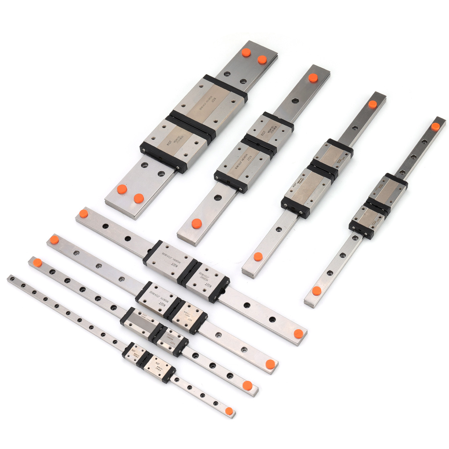
Selecting the correct size for your rail linear application is one of the most critical decisions in mechanical design and automation projects. A rail linear system that is too small will fail under operational stress, leading to equipment damage and costly downtime. Conversely, oversizing your rail linear components wastes budget and increases machine footprint unnecessarily. The key to getting this decision right lies in understanding your specific application requirements, load characteristics, and operational constraints.
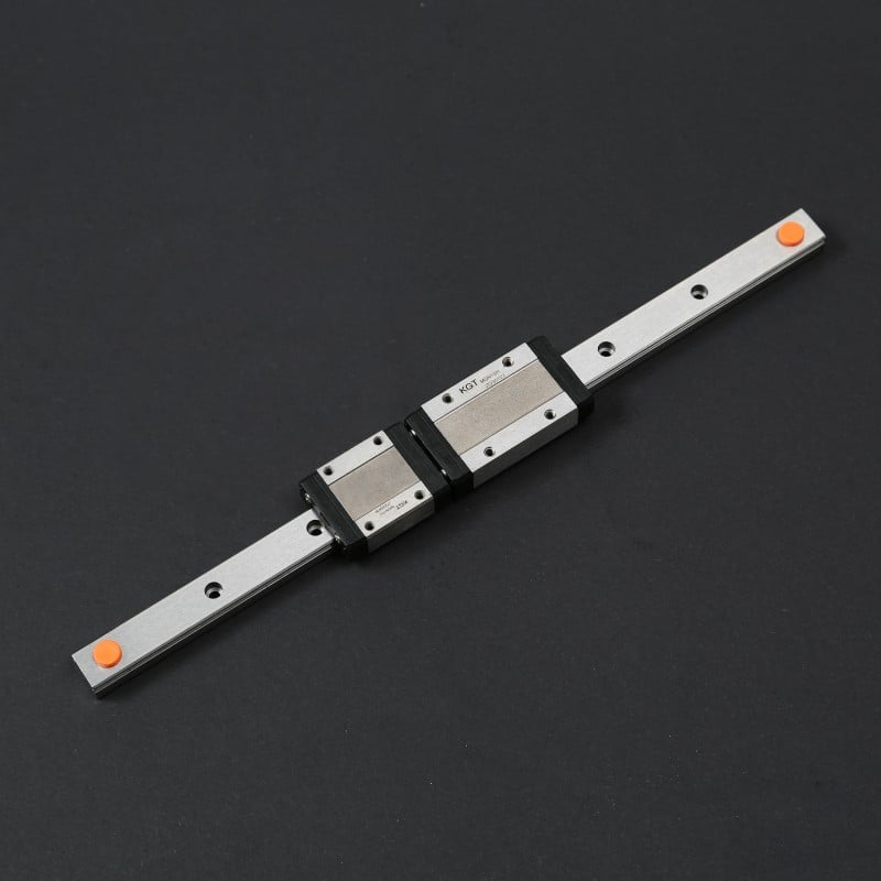
Your rail linear selection process begins with a thorough analysis of the forces your system will experience during normal operation and peak loading scenarios. Every rail linear application demands a different configuration, and mismatches between component size and actual workload represent one of the most common engineering mistakes. This guide walks you through the essential factors that determine what size rail linear solution will serve your project best, ensuring both performance reliability and cost efficiency.
Understanding Load Requirements for Rail Linear Systems
Calculating Static and Dynamic Load Capacity
The foundation of rail linear sizing is understanding both static and dynamic load capacities. Static load refers to the maximum weight that your rail linear system must support when the carriage is stationary or moving at constant velocity. Dynamic load capacity, by contrast, describes the forces your rail linear components experience during acceleration, deceleration, and directional changes. When sizing a rail linear system, engineers must account for the combined weight of the load being moved, the carriage itself, and any additional components mounted to the system. The dynamic load rating of your rail linear guideway must exceed the peak forces generated during your most demanding operational cycle.
Most industrial applications require a safety factor between 1.5 and 3.0 times the calculated maximum load when selecting rail linear components. This safety margin protects your equipment against unexpected spikes in load, manufacturing tolerances, and material fatigue over extended operational periods. When specifying your rail linear system, always consult the load rating tables provided by manufacturers, which detail both static capacity in newtons and dynamic capacity ratings. A properly sized rail linear system maintains component stress levels well below the yield strength of the material, ensuring predictable service life and consistent precision.
Accounting for Shock Loads and Impact Forces
Many applications subject rail linear systems to intermittent shock loads or impact events that exceed normal operating forces. Automated manufacturing lines, material handling equipment, and robotic systems frequently experience sudden directional changes that create momentary force spikes. Your rail linear design must accommodate these transient events without permanent deformation or accelerated wear. Engineers sizing rail linear systems for high-impact applications typically select larger profile dimensions than what average load analysis alone would suggest, providing additional material strength and load-spreading capacity. Impact events that exceed the rail linear system's design envelope can cause permanent damage, including surface spalling, preload loss, and eventual seizure of the carriage.
Stroke Length and Mounting Considerations for Rail Linear Guides
Determining Required Travel Distance
Stroke length is the distance your carriage needs to travel along the rail linear guideway, and this dimension directly influences both the structural integrity of your rail linear system and the overall footprint of your equipment. Longer rail linear strokes introduce greater potential for deflection between the fixed mounting points, particularly when loads are applied away from the carriage centerline. When sizing your rail linear system for extended travel distances, you must account for moment loads that result from offset load positioning. A rail linear guideway that is marginal in load capacity for a short stroke application may become inadequate when stroke length increases significantly. Manufacturers often provide deflection calculations for their rail linear product lines, showing how beam length affects maximum allowable load at specific travel distances.
Your rail linear system must maintain sufficient clearance at both ends of travel to allow for carriage deceleration zones and to prevent mechanical contact between moving and stationary components. Additionally, the rail linear guideway should have adequate exposed length beyond the actual stroke requirement to facilitate installation, maintenance, and future adjustments. Many engineers size their rail linear system with ten to fifteen percent additional length beyond the calculated minimum stroke requirement, providing operational flexibility and design margin.
Preload and Moment Load Effects on Rail Linear Performance
The manner in which forces are applied to your rail linear system significantly influences the required component size. When loads are applied directly along the rail linear guideway axis, the system experiences primarily linear force. However, when loads create moments or lever forces that rotate around the carriage mounting point, the rail linear system experiences complex stress distributions. A rail linear system subjected to significant moment loads requires larger profile dimensions to distribute stresses across a greater material cross-section. Understanding whether your application generates primarily axial loads or significant moment loads is essential for correct rail linear sizing. Poor moment load management leads to accelerated wear on one side of the rail linear guideway, creating uneven friction and eventually causing carriage jamming or misalignment.
Precision Requirements and Speed Considerations
Matching Rail Linear Profile Size to Accuracy Needs
Precision applications demand larger rail linear profile dimensions to maintain positional accuracy over extended operating cycles. High-precision rail linear systems used in semiconductor manufacturing, medical device assembly, and precision measurement require larger bearing blocks and guideway profiles that distribute loads more uniformly and resist deflection more effectively. When your process requires positioning accuracy better than 0.1 millimeter, the rail linear system must be substantially larger than a non-precision application carrying identical loads. Larger rail linear cross-sections provide greater stiffness, which translates directly to better repeatability and reduced drift over thousands of operational cycles. The rail linear guideway profile you select must match both your load requirements and your precision targets simultaneously.
Environmental factors such as temperature fluctuations can affect rail linear system accuracy if the guideway and carriage experience differential thermal expansion. Larger rail linear profiles with greater mass help moderate temperature changes and distribute thermal stresses more evenly through the structure. Premium rail linear systems designed for precision applications often include thermal compensation features and material selections that maintain dimensional stability across wider temperature ranges.
Speed Capabilities and Their Impact on Rail Linear Selection
High-speed rail linear applications require careful consideration of dynamic balance, lubrication effectiveness, and structural rigidity. When your rail linear system operates at elevated speeds, friction heating becomes a significant concern, and inadequate component sizing leads to temperature creep and thermal expansion problems. Larger rail linear profiles generally support higher operational speeds because they offer greater surface area for lubrication distribution and superior heat dissipation characteristics. Applications requiring speeds above 5 meters per second typically demand rail linear systems one profile size larger than static load analysis alone would indicate. Additionally, high-speed rail linear systems benefit from precision preload configurations that minimize radial clearance while maintaining smooth operation across a wide speed envelope.
Practical Application Examples and Decision Factors
Typical Rail Linear Sizing Scenarios
A precision assembly station moving 50-kilogram subassemblies across a 1.5-meter stroke with 0.05-millimeter repeatability requirement would typically require a substantial mid-size rail linear system with robust preload and thermal compensation. Material handling systems that move 500-kilogram loads across shorter strokes with moderate precision needs can often utilize smaller rail linear dimensions with lower operating costs. Industrial automation applications combining high precision, moderate loads, and extended strokes demand carefully balanced rail linear sizing that represents the intersection of all three constraint categories. Your specific rail linear choice depends on honestly evaluating which factors matter most in your application context rather than defaulting to the largest available profile.
Rail linear system selection also involves consideration of duty cycle characteristics. Continuous-operation rail linear systems require larger profile dimensions and superior corrosion protection compared to intermittent-use applications in controlled environments. The total cost of your rail linear system includes not only the initial component purchase but also installation labor, maintenance requirements, and expected service life. Undersizing your rail linear system to save initial capital costs often results in premature failure, expensive downtime, and ultimately higher total cost of ownership compared to correct initial sizing.
FAQ
How do I know if my rail linear system is undersized?
Signs of undersized rail linear systems include carriage binding or resistance that increases over time, audible noise or grinding sounds during operation, visible surface damage or spalling on the rail linear guideway, and loss of positional accuracy or repeatability over normal operating cycles. If your rail linear system shows these symptoms, it should be resized immediately to prevent complete failure and secondary damage to connected equipment.
Can I use a larger rail linear system than my calculations indicate?
Oversizing your rail linear system has minimal performance drawbacks but increases equipment cost, weight, and footprint. However, there are legitimate reasons to choose a larger rail linear profile than minimum calculations indicate, such as accommodating future load increases, improving precision beyond current requirements, or simplifying the design by standardizing on one rail linear size across multiple machines for inventory and maintenance efficiency.
What role does manufacturer guidance play in rail linear sizing?
Manufacturer load rating charts, deflection calculations, and application guidelines are essential reference materials that account for material properties, preload effects, and real-world service experience with specific rail linear product lines. Always consult manufacturer documentation before finalizing your rail linear system size, as different manufacturers may offer different profile options and performance characteristics that influence your optimal selection.