
 EN
EN
Selecting the right linear guide for your project is one of the most consequential engineering decisions you will make during the design phase. A well-matched linear guide delivers precise, repeatable motion, supports the required load capacity, and operates reliably across the intended service life. A poorly matched one, however, leads to accelerated wear, positioning errors, unexpected downtime, and costly redesigns. Whether you are building an automated assembly line, a CNC machining center, a medical imaging device, or a semiconductor handling system, the linear guide you specify will directly shape the performance ceiling of your entire machine.
The challenge is that the market offers an extensive variety of linear guide configurations, load ratings, accuracy grades, preload classes, and material options. Without a structured decision framework, engineers often default to a familiar brand or an arbitrary size selection, which may work acceptably but rarely represents the optimal solution. This article walks you through every critical selection factor, from load analysis and accuracy requirements to environmental suitability and mounting considerations, so you can confidently identify the linear guide that fits your specific project demands.
Understanding the Core Function of a Linear Guide
What a Linear Guide Actually Does in a Machine
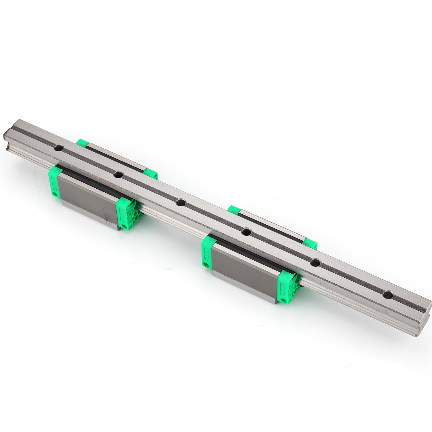
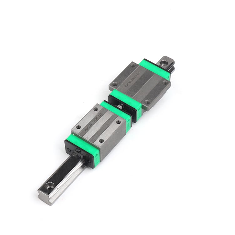
A linear guide is a mechanical component that constrains motion to a single axis while supporting loads applied from multiple directions. Unlike plain sliding guides, a rolling-element linear guide uses recirculating balls or rollers between a rail and a carriage block, achieving dramatically lower friction and far superior positional accuracy. This rolling contact mechanism is what allows high-speed traversal, smooth micro-positioning, and consistent performance across millions of cycles.
The rail is typically mounted to a machine base or structural frame, while the carriage block carries the moving payload. The interface between rail and block defines the stiffness, load capacity, and motion smoothness of the entire axis. When engineers understand this fundamental function clearly, they are better positioned to evaluate whether a given linear guide specification will satisfy the demands placed on that axis in real operating conditions.
It is also worth recognizing that a linear guide does not operate in isolation. It interacts with the drive mechanism, the structural frame, the lubrication system, and the environmental enclosure of the machine. Each of these interactions influences which linear guide specification is truly appropriate for the application at hand.
Key Performance Parameters to Define Before Selection
Before evaluating any specific linear guide product, an engineer must define the performance parameters that the axis must satisfy. These parameters include travel length, maximum speed, acceleration profile, positioning accuracy, repeatability tolerance, and expected service life expressed in total travel distance or operating hours. Each parameter narrows the field of viable linear guide options in a systematic way.
For instance, a high-speed pick-and-place application demands low friction, excellent dynamic load ratings, and minimal thermal expansion sensitivity. A precision optical alignment stage, by contrast, may operate at low speed but requires ultra-high accuracy grades and minimal play. Defining these parameters upfront prevents the common mistake of selecting a linear guide based on size alone without understanding the full performance envelope the application demands.
Load Analysis and Its Impact on Linear Guide Selection
Identifying Load Type, Direction, and Magnitude
Load analysis is the technical foundation of any sound linear guide selection process. A linear guide carriage can experience radial loads, reverse radial loads, lateral loads, and moment loads simultaneously. Each load type acts differently on the internal rolling elements, and a linear guide must be rated to handle the combined effect without plastic deformation of the raceways or premature fatigue failure.
Radial load, which acts perpendicular to the rail mounting surface, is typically the dominant load in most horizontal axis configurations. Lateral loads act parallel to the mounting surface and perpendicular to the direction of travel. Moment loads arise when the center of gravity of the payload is offset from the carriage's geometric center, creating pitch, yaw, or roll moments that impose uneven stress on the four rows of rolling elements within the linear guide carriage.
To perform a proper load analysis, engineers should calculate the equivalent dynamic load acting on each carriage using the actual force components and moment arms. Comparing this equivalent load against the dynamic load rating of the candidate linear guide, combined with a service life calculation based on the rated travel distance, yields a quantitative answer about whether a given size and preload class is appropriate.
Choosing the Right Size Based on Load and Stiffness Requirements
Linear guide size is usually expressed by the rail width in millimeters and corresponds to a defined carriage footprint, rolling element diameter, and rated load capacity. Larger sizes offer higher load ratings and greater rigidity but add weight, footprint, and cost. The selection logic should always begin from the calculated load requirement rather than from assumed size habits carried over from previous projects.
Stiffness is a separate but related consideration. A linear guide that is adequately rated for load may still be too flexible for applications requiring sub-micron positional stability under dynamic forces. In such cases, selecting a larger size or using two carriages per rail instead of one can dramatically increase the effective stiffness of the axis without changing the rail size itself.
When multiple carriages are used on a single rail, the spacing between them also determines how effectively moment loads are distributed. Longer carriage spacing reduces the moment arm and lowers the per-carriage load, extending service life and improving positional stability. This is a practical design optimization that experienced engineers apply specifically when working with compact payloads carrying off-center loads.
Accuracy Grade and Preload Class Selection
Matching Accuracy Grade to Application Precision Requirements
A linear guide is manufactured to specific accuracy grades that define the permissible variation in rail height, rail width, carriage height, and parallelism between rails on the same axis. Common accuracy grade designations range from normal grade through high grade, precision grade, super-precision grade, and ultra-precision grade, with each step representing tighter tolerances and correspondingly higher manufacturing cost.
For general industrial automation, standard or high-grade linear guide products are typically sufficient and provide an excellent balance between performance and cost. Precision grade is appropriate for coordinate measuring machines, laser cutting heads, and similar applications where positional errors in the micrometer range are meaningful. Super-precision and ultra-precision grades are reserved for the most demanding semiconductor and optical applications where tolerances are measured in nanometers.
Selecting an accuracy grade that exceeds what the application genuinely requires adds unnecessary cost and imposes stricter mounting surface preparation requirements. Conversely, selecting an insufficient accuracy grade and then attempting to correct positioning errors through software compensation is an inefficient and often incomplete solution. The right accuracy grade should be specified based on the axis error budget allocated during the machine's overall precision design process.
Understanding Preload and Its Role in Rigidity and Smoothness
Preload refers to the internal compressive force applied to the rolling elements within a linear guide carriage assembly. By eliminating internal clearance and placing the balls or rollers under a controlled compressive load, preload significantly increases the rigidity of the linear guide and reduces the elastic deflection under external loads. Higher preload classes offer greater stiffness but also increase running friction and heat generation.
There are generally three preload classes: light preload, medium preload, and heavy preload. Light preload is appropriate for precision positioning applications where smooth, low-friction travel is paramount and external loads are moderate and well-controlled. Medium preload suits most general industrial applications where a balance between stiffness and friction is needed. Heavy preload is used in heavy-duty machining applications where large cutting forces are transmitted through the linear guide and maximum rigidity is the overriding priority.
Selecting a higher preload than necessary will not improve performance in applications where external forces are light. Instead, it will generate excess heat, increase drive motor requirements, and shorten the lubrication interval. The preload class of a linear guide should be matched to the actual stiffness demand of the axis, not selected conservatively without analysis.
Environmental Conditions and Material Considerations
Evaluating Operating Environment for Linear Guide Durability
The operating environment exerts enormous influence over which linear guide construction is appropriate for a given project. Industrial environments vary widely, from clean, climate-controlled electronics assembly rooms to harsh outdoor construction equipment, food processing facilities with frequent washdowns, or cutting operations that produce metal chips, coolant mist, and abrasive particles. Each environment imposes different risks on the linear guide's sealing system, material integrity, and lubrication retention.
Standard linear guide products use carbon steel rails and carriages with grease lubrication and end seals to exclude moderate contamination. For environments with significant particulate contamination or coolant exposure, additional protection such as metal scrapers, bellows covers, or stainless steel rail covers should be incorporated. These accessories are not optional enhancements in dirty environments — they are essential elements of a reliable linear guide installation.
Temperature is another environmental variable that demands attention during linear guide selection. Elevated operating temperatures, such as those found near furnaces or in high-speed machining enclosures, affect lubricant viscosity, material expansion, and bearing clearance. If a linear guide operates near or above the manufacturer's rated temperature range without appropriate lubricant grade or material specification, service life will be significantly shorter than calculated.
Stainless Steel and Specialty Linear Guide Options for Demanding Conditions
For applications requiring corrosion resistance, such as food processing, pharmaceutical manufacturing, or marine environments, stainless steel linear guide variants are available. These products use corrosion-resistant alloys for rails, carriage bodies, and rolling elements, and often use food-grade lubricants compatible with incidental product contact standards. The load ratings of stainless steel linear guide products are generally lower than equivalent carbon steel versions due to differences in hardness and material properties.
In vacuum or cleanroom environments, the standard linear guide lubrication approach is not suitable. Grease and oil lubricants outgas in vacuum conditions, contaminating the process environment and degrading vacuum quality. Special dry-film lubricants, ceramic-coated rolling elements, or self-lubricating polymer retainers are used in these contexts to allow the linear guide to function reliably without introducing contamination. Selecting the correct variant for cleanroom or vacuum use requires careful consultation of the manufacturer's application specifications.
Practical Mounting, Installation, and Maintenance Guidance
Mounting Surface Preparation and Rail Alignment
Even the highest-quality linear guide will underperform if it is mounted on an inadequate surface. The mounting surface must be flat to within the tolerance specified for the linear guide's accuracy grade, and it must be sufficiently rigid to prevent deflection under operating loads. Machined surfaces are typically required for precision and super-precision grade applications, while ground surfaces are used for the most demanding installations.
When two parallel rails are installed on the same axis, the alignment between them directly determines the carriage's ability to travel smoothly without binding or inducing side loads on the carriages. Misalignment between parallel rails creates a condition where carriages on opposite rails fight each other through the rigid cross-member they support, leading to internal stress, increased friction, and shortened service life. Proper alignment using reference edges, precision spacers, or laser alignment tools is an investment that pays back in extended linear guide service life and consistent machine performance.
Bolt torque during rail installation must also be applied in the sequence and to the values specified by the linear guide manufacturer. Under-torqued bolts allow micro-movement of the rail under dynamic loads, while over-torqued bolts can distort the rail and introduce height variation that degrades positional accuracy. Following the prescribed installation procedure is not a formality — it is a technical requirement for achieving the rated performance of the linear guide.
Lubrication Strategy and Maintenance Interval Planning
Lubrication is the single most important maintenance factor governing the service life of a linear guide. Rolling-element bearing surfaces depend on a thin film of lubricant to prevent metal-to-metal contact, distribute stress, dissipate heat, and exclude contaminants. Insufficient lubrication causes raceway wear, corrosion, and ultimately catastrophic carriage failure. Over-lubrication can cause churning, excess heat, and seal damage that also reduces service life.
Manufacturers provide lubrication interval recommendations expressed in travel distance or time, based on a defined operating condition. In practice, the actual lubrication interval should be adjusted based on operating speed, load, temperature, and contamination level. Automated lubrication systems, which deliver precisely metered lubricant quantities at programmed intervals, are the preferred approach for high-duty-cycle applications where manual re-lubrication would be impractical or inconsistent.
The linear guide you select should be evaluated not only on its initial specifications but also on how easily it integrates with your machine's lubrication strategy. Products that support centralized lubrication port connections, include built-in lubricant reservoirs, or offer easy grease nipple access reduce maintenance burden and help ensure that lubrication is performed consistently throughout the machine's service life.
FAQ
What is the most important factor when selecting a linear guide?
Load capacity is typically the foundational factor, but it must be evaluated alongside accuracy requirements, environmental conditions, and service life expectations. The most important factor ultimately depends on which constraint is most critical in your specific application. For precision instruments, accuracy grade may dominate. For heavy industrial machines, dynamic load rating and rigidity may be paramount. A comprehensive selection process considers all relevant parameters together rather than optimizing for a single criterion.
How do I know if I need a higher preload class for my linear guide?
A higher preload class is warranted when the application requires high rigidity under variable external loads, such as in machining centers where cutting forces change direction and magnitude rapidly. It is also appropriate when the axis must maintain positional accuracy despite dynamic disturbances. If your application primarily involves smooth, low-speed positioning with well-controlled light loads, a light preload linear guide will provide adequate stiffness while keeping friction low and heat generation minimal.
Can a linear guide be used in a vertical orientation?
Yes, a linear guide can be installed and used in a vertical orientation without inherent mechanical limitation. However, vertical installations require special attention to the lubrication strategy, because gravity causes lubricant to drain away from the carriage over time rather than being retained by contact. Frequent re-lubrication intervals, upward-facing grease ports, or automated lubrication systems are recommended for vertical linear guide installations to ensure the rolling element contact surfaces remain properly lubricated throughout service life.
What should I inspect when evaluating linear guide performance after installation?
After installation, the linear guide should be checked for smooth, consistent travel with no binding, jerking, or unusual noise across the full travel range. Positioning repeatability should be verified using a dial indicator or laser interferometer calibrated to the required tolerance. Rail parallelism and carriage running height should be confirmed against the manufacturer's specifications. Any deviation from smooth travel or unexpected positional error often points to mounting surface irregularity, rail misalignment, inadequate lubrication, or contamination ingress that should be addressed before the machine enters production service.