
 EN
EN
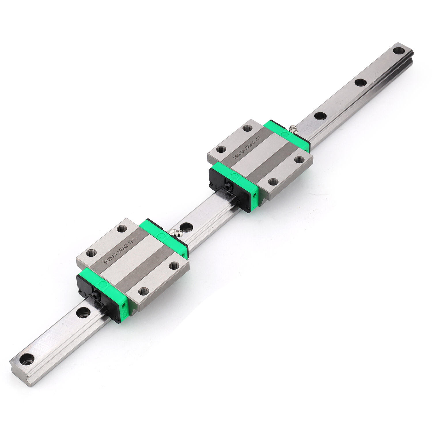
Linear bearing systems are critical components in countless industrial applications, from precision machining centers and automated assembly lines to medical diagnostic equipment and semiconductor manufacturing tools. Despite their seemingly simple design, these systems experience a surprising number of failures that can halt production, compromise product quality, and generate significant maintenance costs. Understanding why linear bearing failures occur and implementing proven prevention strategies is essential for any facility manager, maintenance engineer, or design professional responsible for equipment uptime and operational efficiency.
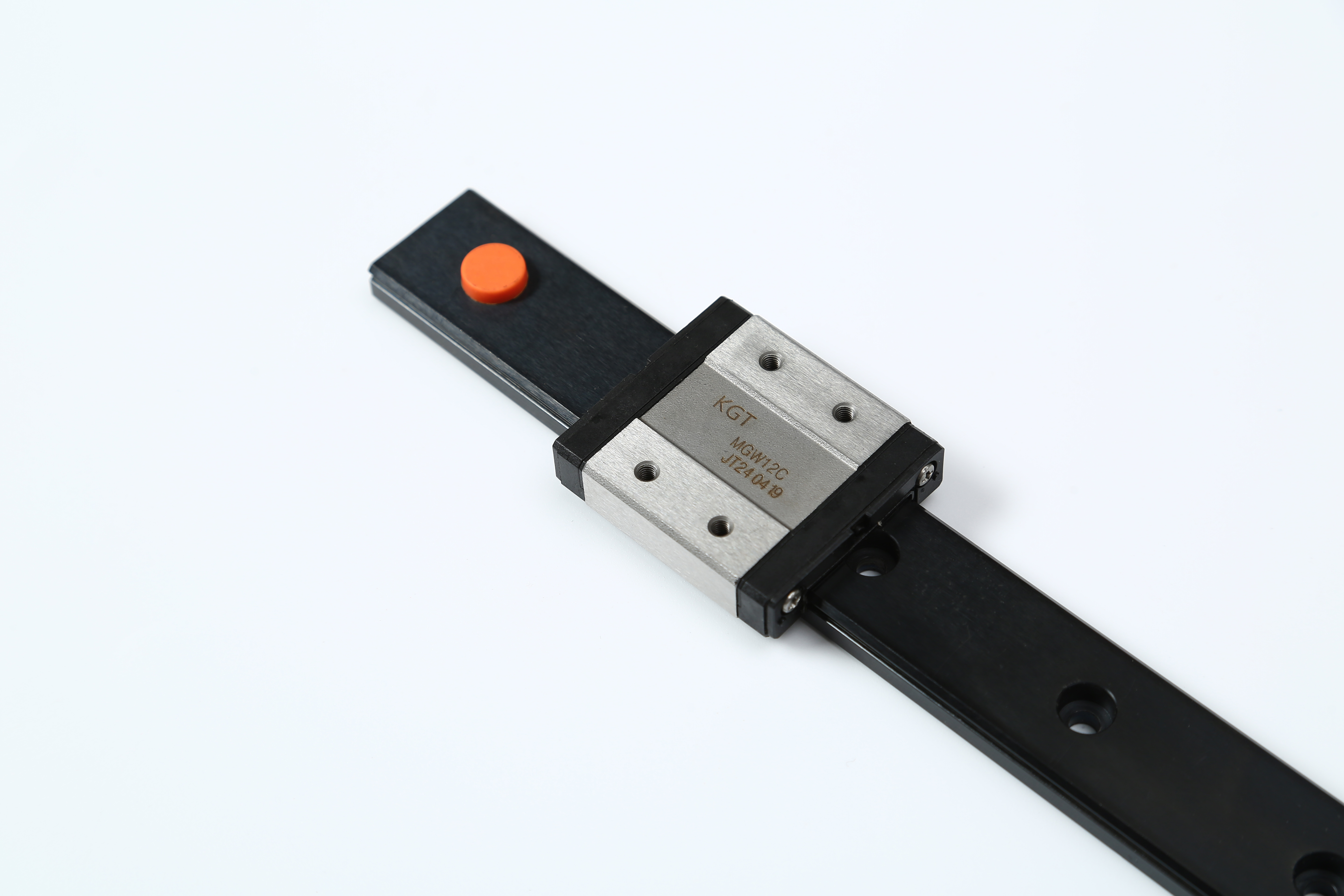
The consequences of linear bearing system failures extend far beyond the immediate breakdown. Unplanned downtime disrupts production schedules, creates backlog in delivery commitments, and forces emergency procurement of replacement parts often at premium prices. More subtly, degraded linear bearing performance gradually reduces positioning accuracy, increases vibration levels, and introduces inconsistencies that manifest as quality defects in finished products. By examining the root causes of these failures and establishing systematic prevention protocols, organizations can dramatically extend bearing life, reduce total cost of ownership, and maintain the precision performance that modern manufacturing demands.
Understanding the Primary Causes of Linear Bearing System Failures
Contamination and Environmental Exposure
Contamination represents the single most common cause of premature linear bearing failure across industrial environments. Abrasive particles such as metal chips, grinding dust, cutting fluid residue, and airborne contaminants infiltrate the bearing raceway and rolling elements, creating three-body abrasion that rapidly degrades precision surfaces. Even microscopic particles measuring only a few microns can initiate wear mechanisms that exponentially accelerate as surface roughness increases and generates additional debris. In machining environments, coolant contamination introduces both particulate matter and chemical corrosion agents that attack bearing materials simultaneously.
Environmental factors compound contamination challenges in many applications. Temperature extremes cause lubricant viscosity changes that reduce protective film thickness, while thermal cycling creates condensation that introduces moisture into bearing assemblies. Humidity exposure leads to corrosion of steel components, particularly when equipment sits idle for extended periods without adequate preservation measures. Chemical exposure from process fluids, cleaning agents, or atmospheric pollutants can degrade seals, attack lubricants, and corrode bearing surfaces even when equipment operates within nominal load and speed parameters.
Inadequate or Improper Lubrication
Lubrication failures rank as the second leading cause of linear bearing system breakdowns, manifesting through multiple failure modes. Insufficient lubricant quantity creates boundary lubrication conditions where metal-to-metal contact occurs between rolling elements and raceways, generating excessive friction, heat, and rapid wear. Conversely, excessive lubrication traps contaminants, increases churning resistance, and generates heat through viscous shearing. The linear bearing assembly requires precisely controlled lubrication that maintains an adequate hydrodynamic film without creating the operational problems associated with over-lubrication.
Lubricant selection errors contribute significantly to premature failures when application requirements are misunderstood or inadequately specified. Using lubricants with incorrect viscosity for the operating temperature range, speed conditions, or load profile results in film breakdown and accelerated wear. Incompatibility between lubricant chemistry and bearing materials or seal compounds causes chemical degradation that destroys lubrication properties and damages components. Mixing incompatible lubricant types during maintenance creates chemical reactions that precipitate additives, alter viscosity, and compromise protective characteristics.
Installation and Alignment Problems
Improper installation practices introduce preload conditions, misalignment stresses, and geometric errors that dramatically shorten linear bearing service life. Mounting surface flatness deviations, parallelism errors, and perpendicularity problems create binding conditions that generate localized stress concentrations and uneven load distribution across rolling elements. When bearing blocks or pillow blocks are bolted to surfaces that deviate from specified tolerances, the resulting distortion preloads certain rolling elements while others carry minimal load, creating uneven wear patterns and premature failure of overloaded components.
Shaft misalignment represents another critical installation error that manifests as cyclic loading, edge loading, and skewing forces that linear bearing systems are not designed to accommodate. Even slight angular misalignment between shaft and bearing axis generates edge loading conditions where contact stress concentrates on the ends of rolling elements rather than distributing uniformly across their length. This edge loading creates stress risers that initiate fatigue cracks, spalling, and rapid degradation of raceway surfaces. Parallel misalignment between multiple bearing blocks supporting a single carriage introduces binding and unequal load sharing that accelerates wear on the most heavily loaded components.
Operating Conditions That Accelerate Linear Bearing Degradation
Overloading and Dynamic Load Exceedance
Operating linear bearing systems beyond their rated load capacity initiates multiple failure mechanisms that drastically reduce service life. Static overload creates permanent deformation of rolling element contact points and raceway surfaces, introducing geometry errors that generate vibration and uneven load distribution during subsequent operation. Dynamic overloading during acceleration, deceleration, or shock loading events creates subsurface fatigue stress that propagates as microcracks eventually leading to spalling and catastrophic failure. Many applications experience intermittent overload conditions during setup, adjustment, or error recovery procedures that cumulatively damage linear bearing components even when normal operating loads remain within specification.
Impact loading deserves special attention as a particularly destructive operating condition that frequently goes unrecognized. Sudden stops, collisions with mechanical limits, or workpiece loading/unloading operations generate force spikes that exceed bearing dynamic load ratings by multiples. These transient events create brinelling damage where rolling elements indent raceway surfaces, forming permanent depressions that generate noise, vibration, and accelerated wear during normal operation. Repeated impact loading accumulates damage even when individual events appear minor, progressively degrading precision and shortening bearing life.
Excessive Speed and Acceleration
Operating linear bearing systems at speeds exceeding design specifications generates heat, increases lubricant shear stress, and introduces dynamic effects that compromise performance and reliability. At elevated speeds, centrifugal forces affect rolling element behavior, altering contact geometry and load distribution patterns. Lubricant film thickness becomes increasingly difficult to maintain as speed increases, particularly with grease-lubricated systems where lubricant migration and churning losses become problematic. Temperature rise from friction and viscous shearing accelerates lubricant degradation, reduces viscosity, and can exceed the thermal limits of seal materials and bearing components.
Acceleration rates impact linear bearing life through inertial loading that supplements applied loads during motion profile execution. High acceleration creates additional dynamic forces that rolling elements and raceways must accommodate, effectively increasing the load spectrum the bearing experiences. Rapid acceleration cycles in pick-and-place applications, high-speed machining centers, and automated material handling systems generate fatigue loading that accumulates over millions of cycles. When combined with inadequate lubrication or contamination issues, these dynamic loading conditions dramatically accelerate wear and reduce the time to failure.
Vibration and External Force Transmission
External vibration transmitted through mounting structures introduces high-frequency cyclic loading that creates fretting wear, false brinelling, and fatigue damage in linear bearing assemblies. When equipment sits idle while nearby machinery operates, transmitted vibration causes minute oscillatory motion between rolling elements and raceways. This micro-motion occurs without sufficient displacement to generate hydrodynamic lubrication, resulting in fretting corrosion that creates wear debris and surface damage. The resulting surface roughness increases friction, generates heat during subsequent operation, and establishes conditions for accelerated degradation.
Structural resonance conditions amplify vibration effects when excitation frequencies coincide with natural frequencies of the bearing system or supporting structure. Resonant vibration magnifies displacement amplitudes, increases dynamic forces, and creates severe operating conditions that rapidly damage linear bearing components. Poorly damped structures transmit shock loads and impulse forces that would otherwise dissipate, subjecting bearings to load spectra far exceeding normal operating conditions. Identifying and eliminating resonance conditions through structural modification or vibration isolation represents a critical prevention strategy for extending bearing life.
Systematic Prevention Strategies for Extending Linear Bearing Life
Contamination Control and Environmental Protection
Implementing effective contamination control begins with physical barriers that prevent particle ingress into linear bearing assemblies. Sealed bearing designs with integral contact seals or non-contact labyrinth configurations provide the first line of defense against environmental contaminants. Supplementing bearing seals with external bellows covers, telescoping way covers, or wiper systems creates multiple barriers that dramatically reduce contamination exposure. In particularly harsh environments, positive pressure enclosures using filtered air maintain a clean atmosphere around bearing assemblies, preventing ingress of airborne particles and moisture.
Regular cleaning protocols remove accumulated contaminants before they can migrate into bearing assemblies and initiate wear mechanisms. Establishing scheduled cleaning intervals based on operating conditions, environmental exposure, and contamination monitoring prevents buildup that would otherwise overwhelm seal systems. Using appropriate cleaning methods and agents that do not damage seals or degrade lubricants maintains protective barriers without introducing new problems. In applications where contamination exposure is unavoidable, increasing inspection frequency and implementing condition-based maintenance allows early detection of contamination-related degradation before catastrophic failure occurs.
Optimal Lubrication Management
Selecting the correct lubricant for specific operating conditions, load profiles, and environmental factors forms the foundation of effective linear bearing lubrication management. Grease lubrication offers simplicity and long service intervals for moderate-speed applications with adequate relubrication access, while oil lubrication provides superior cooling and contamination flushing for high-speed or heavily loaded systems. Lubricant viscosity must match operating temperature ranges to maintain adequate film thickness across the expected temperature envelope. Additive packages should be selected based on environmental challenges such as corrosion protection requirements, extreme pressure conditions, or compatibility with seal materials and coatings.
Establishing systematic relubrication schedules based on operating hours, cycle counts, or condition monitoring prevents lubricant starvation while avoiding over-lubrication problems. Automated lubrication systems deliver precise quantities at programmed intervals, ensuring consistent bearing protection without requiring operator intervention or creating the variability associated with manual lubrication. Monitoring lubricant condition through oil analysis or grease sampling programs identifies degradation trends before lubrication failure occurs, enabling proactive lubricant replacement rather than reactive failure response. Documentation of lubrication activities creates historical records that support reliability analysis and continuous improvement initiatives.
Precision Installation and Alignment Practices
Achieving specified installation tolerances begins with proper preparation of mounting surfaces to meet flatness, perpendicularity, and surface finish requirements. Machining or grinding mounting surfaces to achieve required geometric tolerances eliminates distortion sources that would preload bearings or create misalignment conditions. Using precision measurement tools including dial indicators, laser alignment systems, or coordinate measuring equipment verifies that mounting surfaces meet specifications before bearing installation proceeds. Surface cleanliness protocols remove contaminants, burrs, and protective coatings that would interfere with proper seating and introduce geometric errors.
Following manufacturer installation procedures and torque specifications ensures proper bearing preload, mounting interface integrity, and alignment between system components. Torque sequences that progressively tighten mounting fasteners prevent distortion and uneven clamping forces that would compromise bearing geometry. Alignment verification after installation but before system operation identifies problems when correction is straightforward rather than after wear patterns have developed. Implementing installation checklists and requiring verification sign-off creates accountability and ensures critical steps are not overlooked during assembly or maintenance activities.
Condition Monitoring and Predictive Maintenance Approaches
Vibration Analysis and Signature Recognition
Vibration monitoring provides early warning of developing linear bearing problems by detecting characteristic frequency signatures associated with specific defect types. Accelerometers mounted on bearing housings or adjacent structures capture vibration spectra that reveal rolling element defects, raceway damage, misalignment, and lubrication problems before they progress to failure. Establishing baseline vibration signatures during commissioning creates reference standards for comparison during subsequent monitoring intervals. Trending vibration amplitude and frequency content over time identifies gradual degradation that might otherwise escape detection until catastrophic failure occurs.
Advanced diagnostic techniques including envelope analysis, time waveform analysis, and orbit analysis extract detailed information about bearing condition from vibration signals. Envelope analysis enhances detection of high-frequency impacts generated by rolling element defects, enabling identification of incipient spalling or cracking before visible damage appears. Comparing vibration characteristics across multiple linear bearing assemblies in similar applications identifies outliers that require investigation, focusing maintenance resources on bearings most likely to fail. Automated monitoring systems with alarm thresholds trigger notifications when vibration levels exceed acceptable limits, enabling immediate response before minor problems escalate.
Temperature Monitoring and Thermal Analysis
Temperature monitoring detects friction increases, lubrication problems, and overload conditions that generate heat in linear bearing assemblies. Contact temperature sensors, infrared thermography, or thermal imaging cameras identify temperature rises that indicate developing problems. Establishing normal operating temperature ranges for specific applications creates baselines for comparison, with deviations triggering investigation and corrective action. Temperature differentials between similar bearings operating under comparable conditions highlight individual assemblies experiencing abnormal friction or inadequate lubrication.
Thermal trending over time reveals gradual degradation as wear increases friction and reduces heat dissipation efficiency. Sudden temperature increases indicate acute problems such as lubrication failure, contamination ingress, or overload events that demand immediate attention. Correlating temperature data with operational parameters including load cycles, speed changes, and environmental conditions helps identify root causes and optimize operating parameters to minimize thermal stress. Integrating temperature monitoring with other condition indicators including vibration and acoustic emission creates comprehensive bearing health assessment that improves diagnostic accuracy.
Acoustic Emission and Ultrasonic Detection
Acoustic emission monitoring detects high-frequency stress waves generated by crack propagation, spalling events, and friction phenomena in linear bearing systems. This technique identifies developing defects at very early stages when damage remains localized and corrective action can prevent catastrophic failure. Ultrasonic sensors detect changes in friction levels and lubrication film thickness, providing early warning of lubrication degradation before temperature or vibration signatures become apparent. Acoustic monitoring complements traditional vibration analysis by detecting phenomena occurring at frequencies above the range of conventional accelerometers.
Portable ultrasonic instruments enable rapid bearing condition assessment during routine maintenance rounds without requiring permanent sensor installation. Comparing ultrasonic amplitude and frequency characteristics between bearings identifies anomalies that warrant detailed investigation. Establishing condition severity scales based on ultrasonic signal characteristics helps maintenance personnel prioritize interventions and schedule repairs before failures occur. Training maintenance teams in acoustic signature interpretation builds organizational capability for proactive bearing management that extends equipment life and reduces unplanned downtime.
Design Optimization and Application Engineering Best Practices
Proper Bearing Selection and Sizing
Selecting linear bearing systems with adequate load capacity, appropriate accuracy grades, and suitable sealing configurations for specific applications prevents premature failures caused by specification inadequacy. Load calculations must account for static loads, dynamic loads, acceleration forces, and external moments that bearing assemblies will experience during operation. Applying appropriate service factors based on operating conditions, duty cycles, and reliability requirements ensures bearings have sufficient margin to accommodate load variations and unexpected conditions. Consulting manufacturer load ratings, life calculations, and application guidelines helps engineers make informed selection decisions that balance performance requirements with cost considerations.
Accuracy grade selection impacts both bearing life and system performance, with higher accuracy bearings providing better load distribution and lower friction but commanding premium prices. Matching bearing accuracy to application precision requirements avoids over-specification that increases costs without providing functional benefits while preventing under-specification that compromises performance. Seal configuration selection balances contamination protection against friction and maintenance requirements, with contact seals providing maximum protection at the expense of higher friction and periodic replacement. Non-contact seals minimize friction and maintenance but provide less contamination resistance, requiring careful evaluation of environmental exposure.
System Integration and Support Structure Design
Designing support structures with adequate rigidity prevents deflection that would compromise linear bearing alignment and introduce binding conditions. Finite element analysis during design phases identifies potential deflection problems and guides structural reinforcement to maintain bearing alignment under operating loads. Minimizing cantilever distances between bearing supports reduces bending moments and distributes loads more evenly across bearing assemblies. Incorporating adjustment provisions enables precise alignment during installation and provides capability for realignment if settling or thermal effects introduce geometry changes over time.
Mounting interface design significantly influences linear bearing performance and reliability. Providing adequate mounting surface area distributes clamping forces and prevents localized stress concentrations that could distort bearing housings. Specifying appropriate mounting fastener sizes, materials, and locking features ensures secure attachment that maintains alignment under dynamic loading and vibration exposure. Incorporating location features such as dowel pins or precision-ground shoulders provides positive positioning that maintains alignment during assembly and prevents shift during operation. These design details require minimal additional cost during fabrication but dramatically improve bearing reliability throughout service life.
Operating Parameter Optimization
Optimizing motion profiles to minimize peak acceleration and jerk rates reduces dynamic forces that contribute to linear bearing wear and fatigue loading. Modern motion controllers enable sophisticated trajectory planning that smoothly transitions between motion segments while meeting cycle time requirements. Evaluating trade-offs between cycle time and bearing loads helps identify operating parameters that optimize productivity while maintaining acceptable bearing life. Implementing soft start and soft stop functions eliminates shock loading during motion initiation and termination, extending bearing life with minimal impact on overall equipment productivity.
Load balancing strategies distribute forces across multiple linear bearing assemblies rather than concentrating loads on individual components. Designing systems with symmetric loading configurations equalizes bearing wear and extends overall system life. Incorporating load-sharing mechanisms ensures that manufacturing tolerances and alignment variations do not cause one bearing to carry disproportionate load while others remain lightly loaded. Regular evaluation of load distribution through measurement or analysis identifies opportunities for adjustment or redesign that can substantially extend bearing service intervals and reduce maintenance costs.
FAQ
What are the warning signs that a linear bearing is beginning to fail?
Early warning signs of impending linear bearing failure include increased operating noise levels, particularly grinding or rumbling sounds that indicate surface damage or contamination. Rough or inconsistent motion feel during manual movement suggests wear or damage to rolling elements and raceways. Rising operating temperatures above normal baseline levels indicate increased friction from lubrication problems or wear progression. Visible contamination around seals or evidence of lubricant leakage suggests seal degradation that will allow contaminant ingress. Finally, declining positioning accuracy or repeatability often indicates bearing wear that has progressed to affect geometric precision.
How often should linear bearing systems be inspected and maintained?
Inspection and maintenance frequency depends on operating conditions, environmental exposure, and duty cycle severity. Critical applications in harsh environments may require weekly visual inspections and monthly detailed assessments including vibration measurement and lubrication checks. Moderate-duty applications in controlled environments might extend inspection intervals to quarterly or semi-annual schedules. Establishing condition-based maintenance triggers based on operating hours, cycle counts, or monitored parameters optimizes resource allocation by focusing attention on bearings that actually need service rather than following arbitrary time intervals. Manufacturer recommendations provide starting points that should be adjusted based on actual operating experience and failure history analysis.
Can linear bearings be rebuilt or refurbished after wear occurs?
Most linear bearing designs are not economically rebuildable once significant wear has occurred because precision grinding and heat treatment requirements make refurbishment costs approach or exceed new bearing prices. Minor surface corrosion or contamination damage may sometimes be addressed through cleaning and relubrication for bearings that have not experienced actual wear of precision surfaces. Shaft replacement represents a cost-effective refurbishment option when linear bearing shafts show wear but bearing blocks remain serviceable. In high-value specialized applications with custom bearing designs, manufacturer refurbishment programs may offer viable economic alternatives to complete replacement, though most standard catalog bearings are replaced rather than rebuilt when wear limits are reached.
What is the typical service life expectancy of properly maintained linear bearing systems?
Service life varies dramatically based on operating conditions, loading, speed, and maintenance quality, making generalizations difficult without specific application details. Under ideal conditions with proper loading, lubrication, and contamination control, linear bearing systems commonly achieve 20,000 to 50,000 kilometers of travel or more. High-speed or heavily loaded applications may reduce life expectancy to 10,000 kilometers or less, while lightly loaded precision applications in clean environments sometimes exceed 100,000 kilometers. Manufacturer life calculations based on load ratings and operating parameters provide estimated L10 life values representing the travel distance at which 10 percent of a bearing population would be expected to show fatigue failure, offering useful planning guidance for maintenance scheduling and spare parts inventory management.
Table of Contents
- Understanding the Primary Causes of Linear Bearing System Failures
- Operating Conditions That Accelerate Linear Bearing Degradation
- Systematic Prevention Strategies for Extending Linear Bearing Life
- Condition Monitoring and Predictive Maintenance Approaches
- Design Optimization and Application Engineering Best Practices
- FAQ