Quick Links

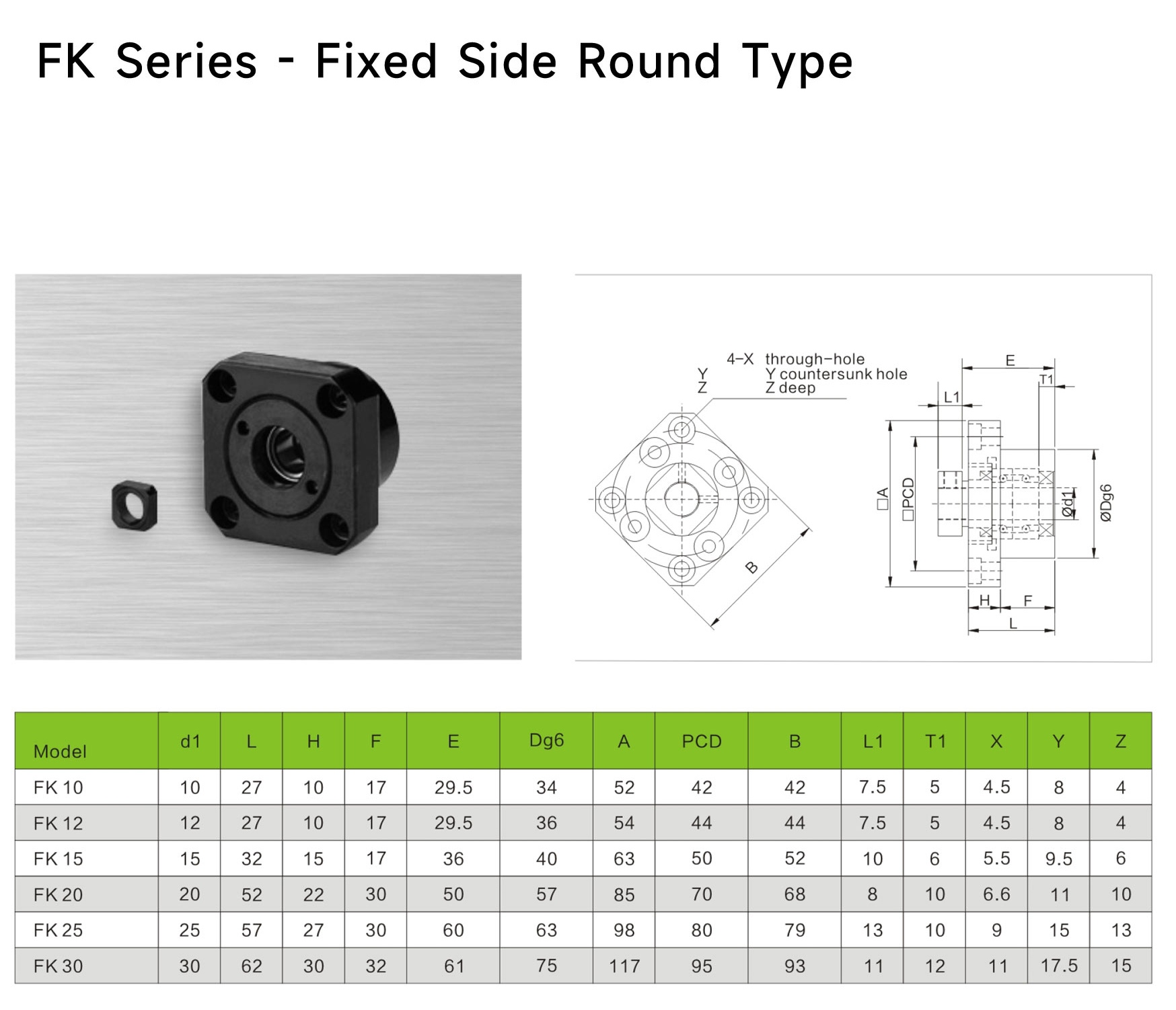
"FK" is another mainstream standard form of the ball screw "support side (floating end)" support unit. It is functionally and positionally identical to "BF" but differs in internal structure and appearance.
Positioning: Standard-type ball screw floating end (free end) support unit. Like BF, it is used at the non-drive end of the screw, allowing axial thermal expansion float and primarily withstanding radial loads.
Nomenclature Interpretation:
Core Value: Provides a structurally compact, installation-stable, economical, and reliable standard floating-end solution. It is the historically longest-standing and most classic pairing combination with the BK fixed end.
The FK unit's design philosophy is simplicity, robustness, and practicality:
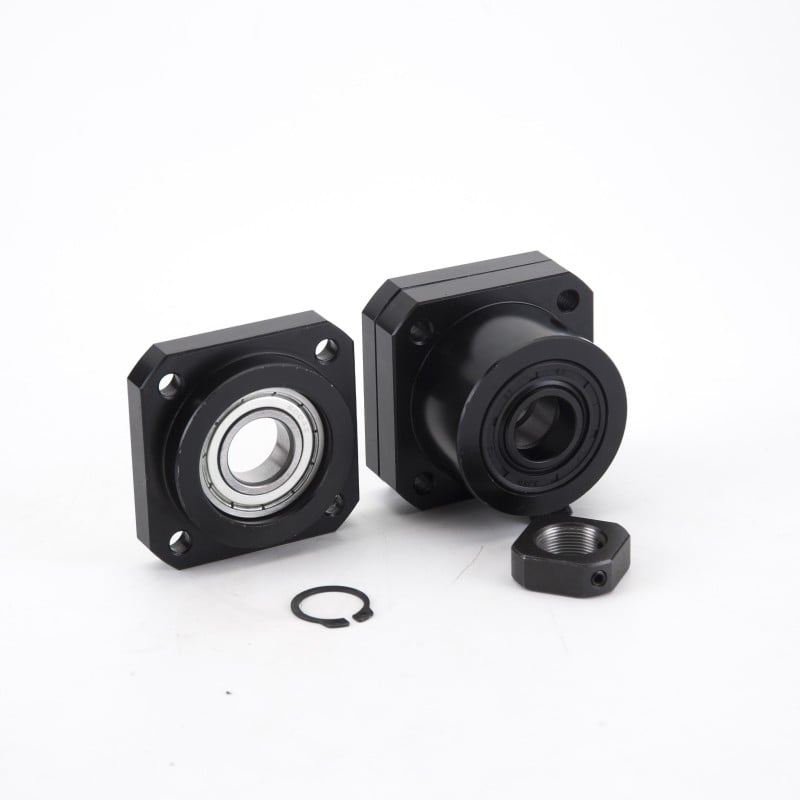
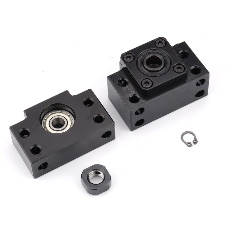
Square Flange Housing:
The housing is a monolithic square flange block, fixed via four mounting holes at the corners. This structure offers good torsional resistance and high mounting rigidity, making it the most common appearance in industrial equipment.
Internal Bearing and Floating Structure:
Sealing and Lubrication:
Connection to Screw Shaft:
The screw shaft end typically requires machining a snap ring groove for installing a retaining ring (snap ring). This ring's function is to prevent the bearing inner ring from accidentally sliding off the shaft end, but it does not restrict axial movement of the screw due to thermal expansion (the bearing inner ring can slide on the shaft). This is a key design commonality between FK and BF.
| Feature | FK (Square Flange Floating End) | BF (Round Flange Floating End) | EF (Eccentric Locking Floating End) |
| Housing Shape | Square flange, strong torsional resistance, stable installation. | Round flange, flexible installation, space-saving. | Mostly round or square, but core feature is the eccentric locking sleeve. |
| Screw Shaft Requirement | Requires a snap ring groove for installing a retaining ring to prevent detachment. | Usually also requires a snap ring groove or small step. | Plain shaft is sufficient, no machining required. |
| Locking Method | Clearance fit + snap ring for anti-detachment. | Similar to FK. | Radial friction locking (eccentric sleeve). |
| Classic Pairing | BK (square flange fixed end). | Typically paired with the same series round flange fixed end. | EK (eccentric locking fixed end). |
| Design Focus | General industrial standard, robust and durable, good cost-effectiveness. | Standard floating end in BF/BK systems, performance comparable to FK, different appearance. | Optimized for plain shaft systems, emphasizes installation convenience. |
| Selection Logic | Preferred when the fixed end uses BK and the screw shaft can be machined with a snap ring groove. | Selected when the fixed end uses the same series round flange type. | Mandatory when the fixed end uses EK and a plain shaft screw is used. |
Simple Selection Guide:
FK's application is as widespread as BK/BF, serving as the absolute mainstay in general industry:
The FK support unit is the "classic" and "basic" model in the world of ball screw floating ends. It may not feature dazzling new technology, but its robust square flange structure, mature and reliable design, and excellent cost-effectiveness have ensured its enduring presence in the industrial field, making it the "gold standard" paired with the BK fixed end. Choosing FK means opting for a time-tested technical path with minimal risk and optimal cost, a fundamentally sound decision to ensure long-term stable operation of equipment.
BF series ball screw end support
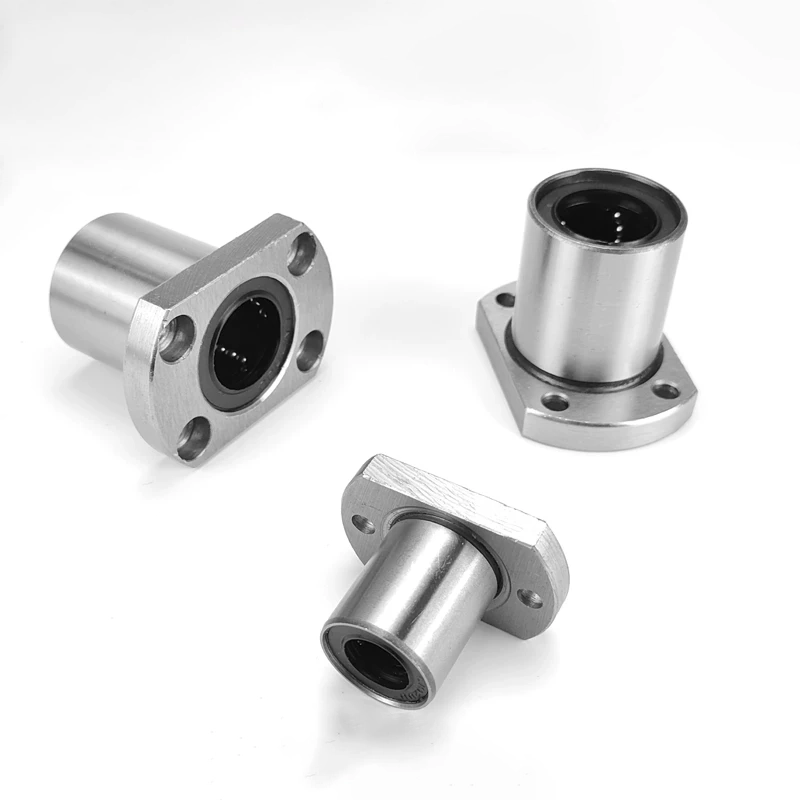
Linear Bearings LMK/LMF/LMH Series
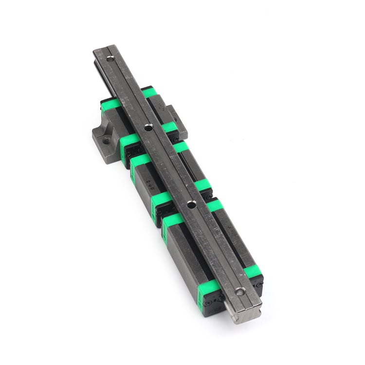
EGW Series Linear Guideway
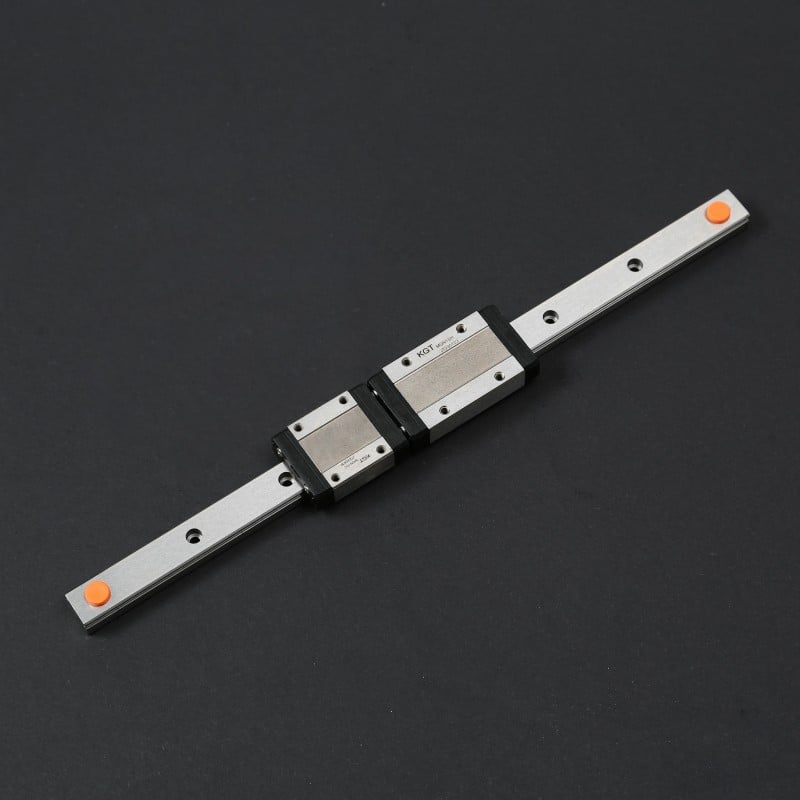
MGN Series Linear Guideway