Quick Links
Selecting the appropriate linear guide model is one of the most critical decisions in motion system design. As a mechanical engineer with over 20 years of experience in precision automation, I’ve seen countless applications fail not due to poor control or drive systems, but because the wrong linear guide was chosen—leading to premature wear, reduced accuracy, or even catastrophic failure. The choice of linear guide directly impacts performance, reliability, cost, and maintenance cycles.
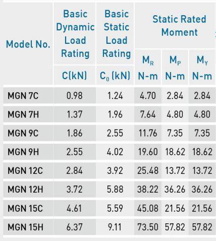
The first step in selecting a linear guide is determining the load conditions. Linear guides are rated based on dynamic load capacity (C) and static load capacity (C₀). Dynamic load refers to the maximum load that allows a nominal life of 50 km under cyclic operation. Static load indicates the maximum force the guide can withstand without permanent deformation during shock or standstill.

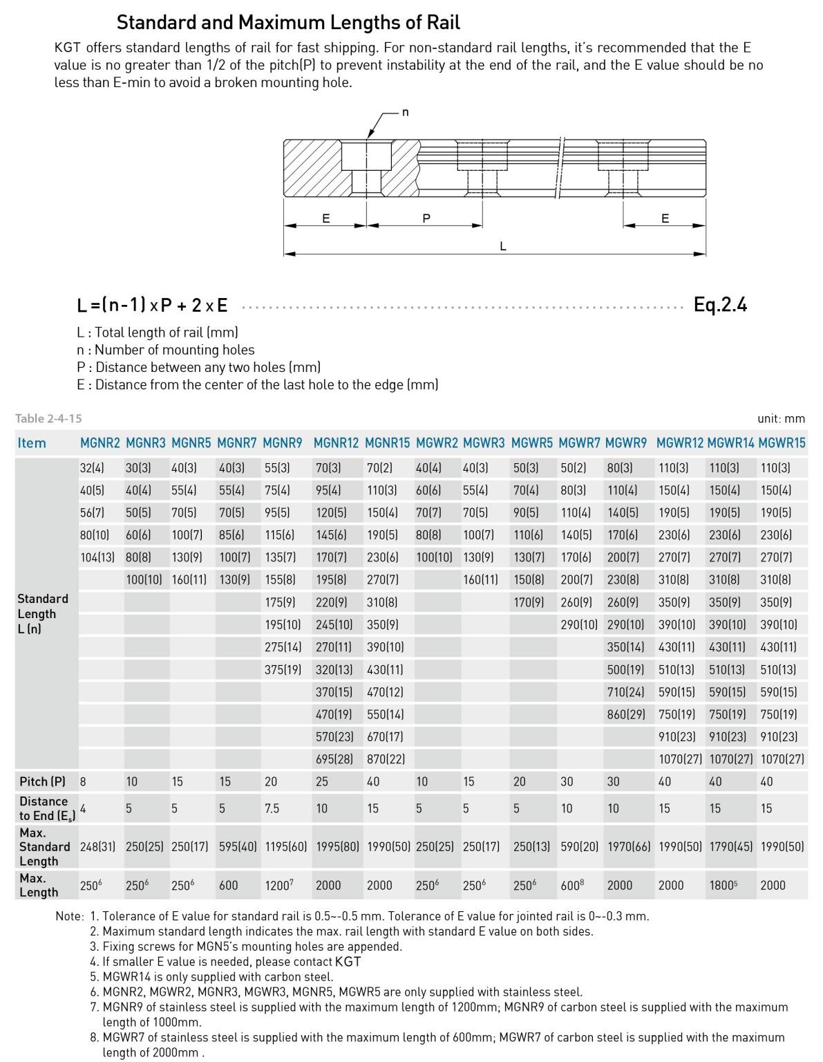
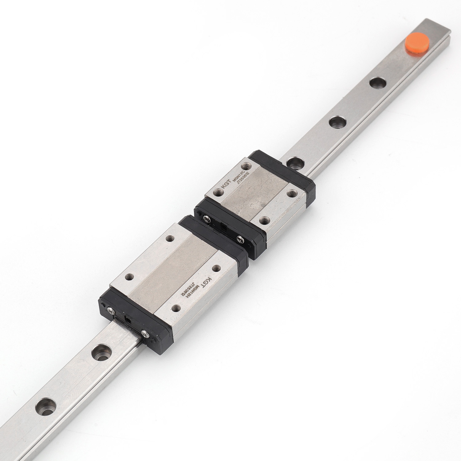
Linear guide size is typically defined by the profile width (e.g., 15 mm, 20 mm, 30 mm, etc.), which correlates with load capacity and rigidity. Narrow Miniature Guides (e.g., 15–20 mm width) are suitable for compact applications such as pick-and-place robots or small gantry systems. They offer low friction due to circular arc grooves and are available in lengths up to 2 meters.
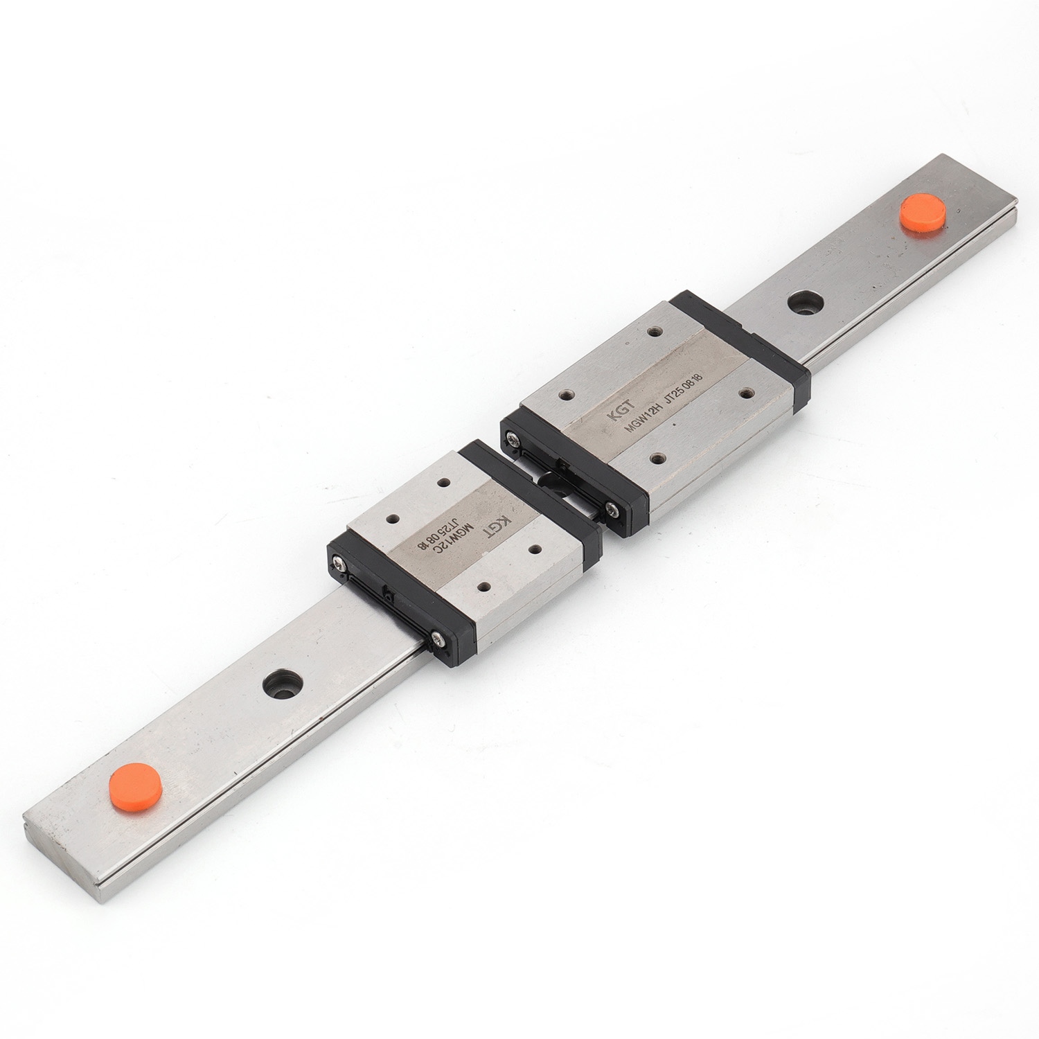
In contrast, Wide Miniature Guides provide higher rigidity at load moments across the rail direction, making them ideal for applications requiring both compactness and strength. For longer strokes—up to 4 meters—undivided rails are standard, minimizing joint effects and ensuring smooth motion over extended travel.
When choosing stroke length, consider whether segmented rails (with joints) are acceptable. While segmented rails reduce costs, they introduce potential misalignment and noise. For high-precision applications, continuous rails or endless rails (F-rails) with arbitrary segmentation are preferred.
High-speed applications demand guides with low friction and optimized rolling element design. MG’s ball chain technology—where rolling elements are separated into individual chains—reduces vibration and noise levels significantly. This design also ensures smoother movement, lower operating temperatures, and longer service life.
Environmental factors play a crucial role in guide selection. If your application operates in a dusty, humid, or corrosive environment, corrosion-resistant materials are essential. MG offers profile rails and carriages made from corrosion-resistant materials as standard, including stainless steel or coated variants like DURALLOY TDCII. These coatings enhance durability in harsh settings such as food processing, marine environments, or chemical handling.
Sealing options are equally important. MG provides diverse sealing kits, including plastic caps, brass caps, cover strips, or bellows, to protect against contamination. For cleanroom applications, sealed versions with low outgassing properties are available. Manual and pneumatic clamping elements further improve holding force and stability during non-motion phases.
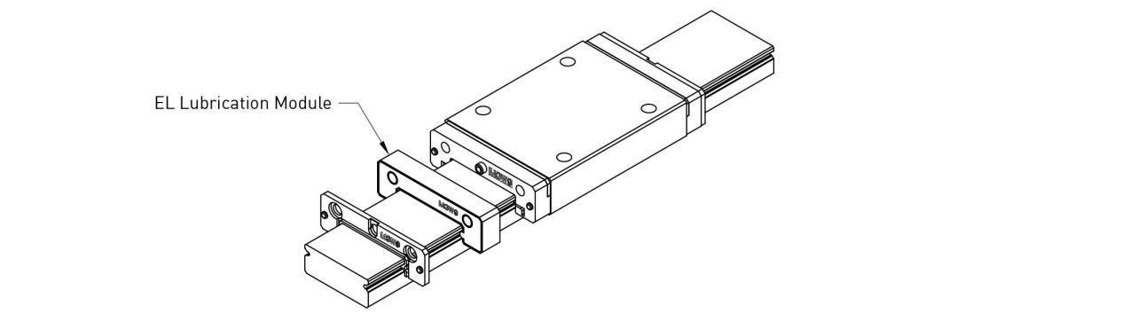
Lubrication is another key factor. High-performance lubricants tailored to specific operating conditions—such as high temperature, high load, or vacuum environments—are available. Some models support integrated lubrication systems that ensure consistent oil delivery, reducing downtime and extending component life.
One of the strengths of MG linear guides is their adaptability. Accessories such as scaling kits allow individual adaptation of carriages to match application-specific requirements. This includes custom mounting holes, flanges, or sensor integration points. For OEMs, this flexibility reduces design time and simplifies integration.
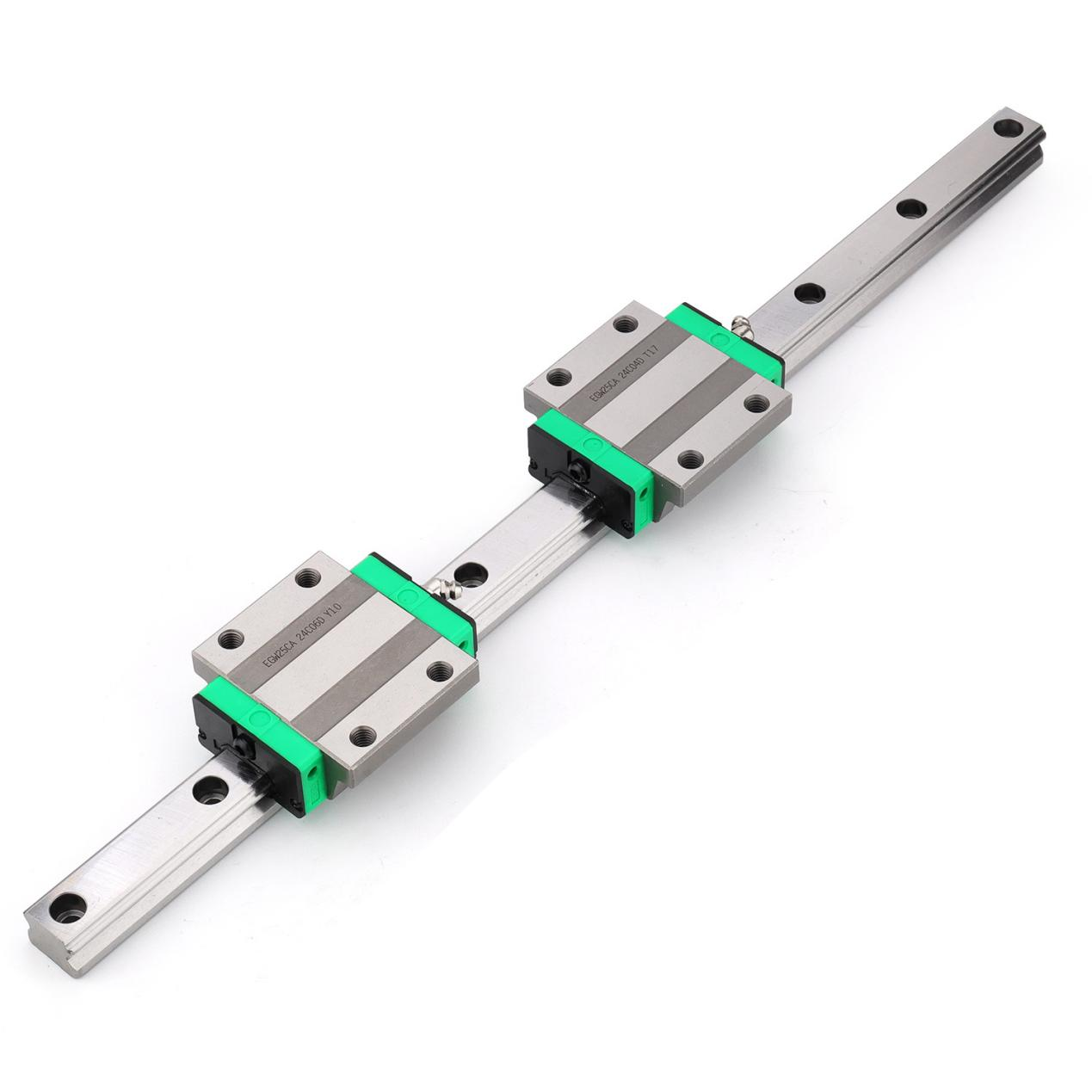
- Standard Linear Guides: Ideal for general-purpose use with balanced load distribution.

- Wide Standard Linear Guides: Best for high-load, high-moment applications like heavy-duty machining centers.
- Narrow Miniature Guides: Perfect for space-constrained designs such as lab automation or micro-positioning stages.
- Wide Miniature Guides: Suitable for compact systems needing high rigidity, such as medical devices or inspection machines.
MG Linear Guides, with their advanced ball chain technology, wide range of sizes, and robust accessory options, represent a benchmark in precision motion systems. Whether designing a high-speed packaging line or a delicate surgical robot, the right linear guide ensures that every millimeter of motion is precise, predictable, and dependable.